Basic TIA Portal & Factory IO Project

Introduction to Siemens TIA Portal and Factory IO
In the dynamic world of industrial automation, the synergy between software and simulation is indispensable for creating efficient and effective control systems. In this tutorial, we embark on a journey to merge the power of TIA Portal, Siemens's comprehensive programming environment, with Factory IO, a simulation tool. Together, we will construct a basic conveyor system, demonstrating the art of tying TIA Portal tags to push buttons and lights, as well as the intricate process of developing PLC programming for motor control. By the end of this guide, you'll have a tangible understanding of how to unite these two powerful tools, paving the way for more complex automation projects.
Prerequisites
You’ll need to have a few items to follow this tutorial:
- TIA Portal V15 | Note - The process is the same for other versions of TIA Portal.
- Net-To-PLC-Sim | Note: It is necessary for simulating a real PLC when a physical PLC is not available.
- Factory IO.
Factory IO side – Configurations
Following this Siemens TIA Portal Factory IO Tutorial, you will be able to create a scene quickly.
Step 1 – Create a Scene
Step 1.1:
We aim to develop a comprehensive project encompassing many components, providing a practical opportunity to learn and program each element. To achieve this, we will create a color-sorting project by counting all materials, allowing us to delve into the intricacies of programming within an industrial context.
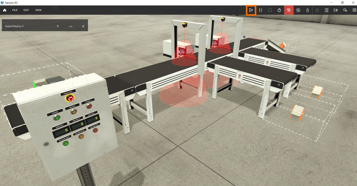
Let's take a closer look at the setup and control panel for this project.
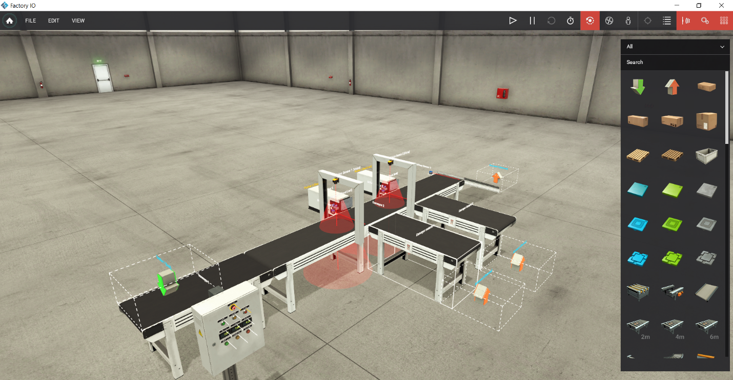
In the figure above, we have set up two primary “conveyors.” One is 2 meters, and the other is 6 meters. Additionally, we've integrated two 2-meter “conveyors” for handling the sorted materials using pushers. Our setup incorporates three “diffuse sensors,” where two of them serve as indicators to detect the material's presence at the pusher, while the third sensor is to count exit material. To complete our configuration, we've added two “vision sensors,” a critical component in our material sorting process. |Note: We will implement a counting system for the two sorted materials, while the third material will be counted as an “exit material” in the project. We can utilize two additional diffuse sensors at the end of the two sorted conveyors to signal the successful exit of sorted materials; we will not be configuring them for this project.
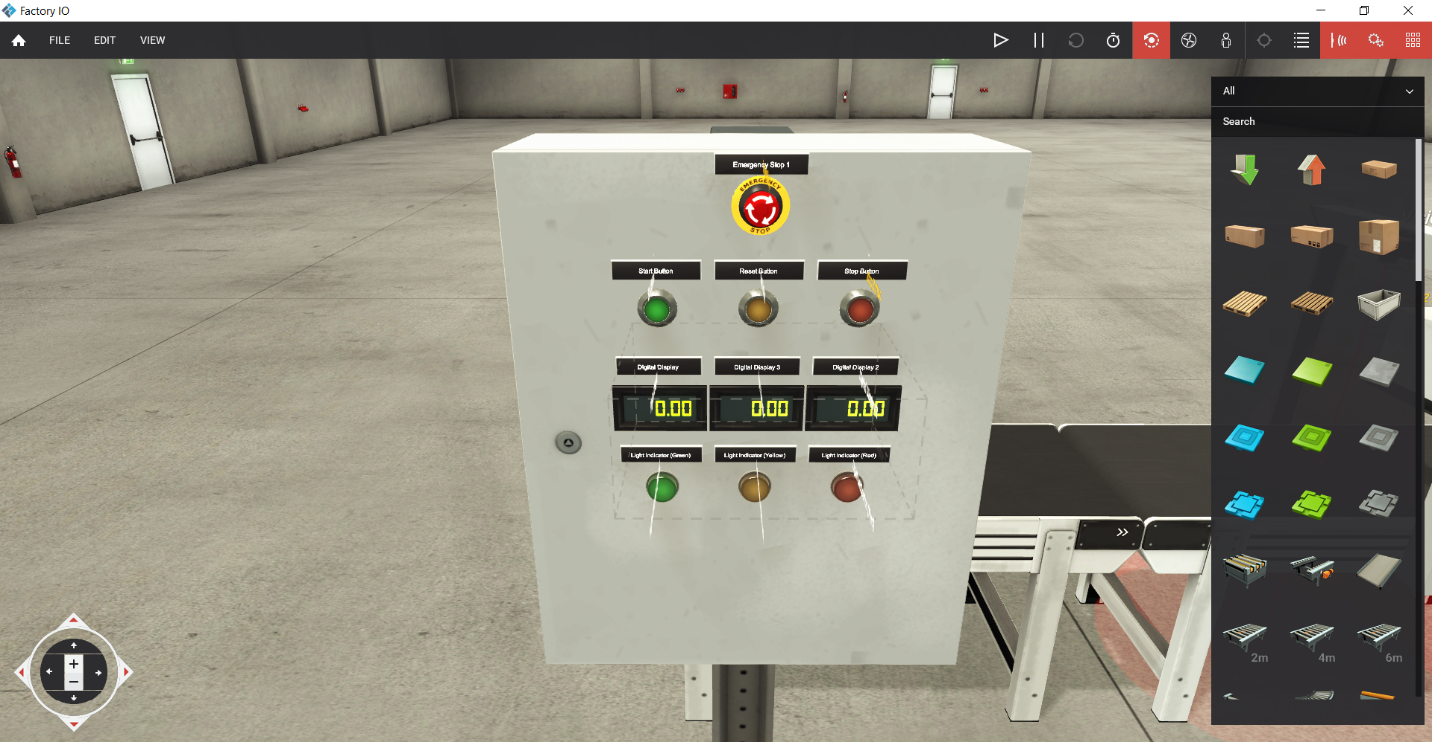
In the figure above, the control panel features three push buttons. The first button is the “Start button,” the second is the “Stop button,” and the third is the “Reset button” to reset the counters. Additionally, we have an “emergency stop button” for immediate system shutdown. It also includes three “indicators”: one indicating system operation, another in red signifying a system stop, and a yellow indicator for an emergency stop condition.
Note: you can modify the names of Inputs/Outputs by clicking on the name and changing it easily.
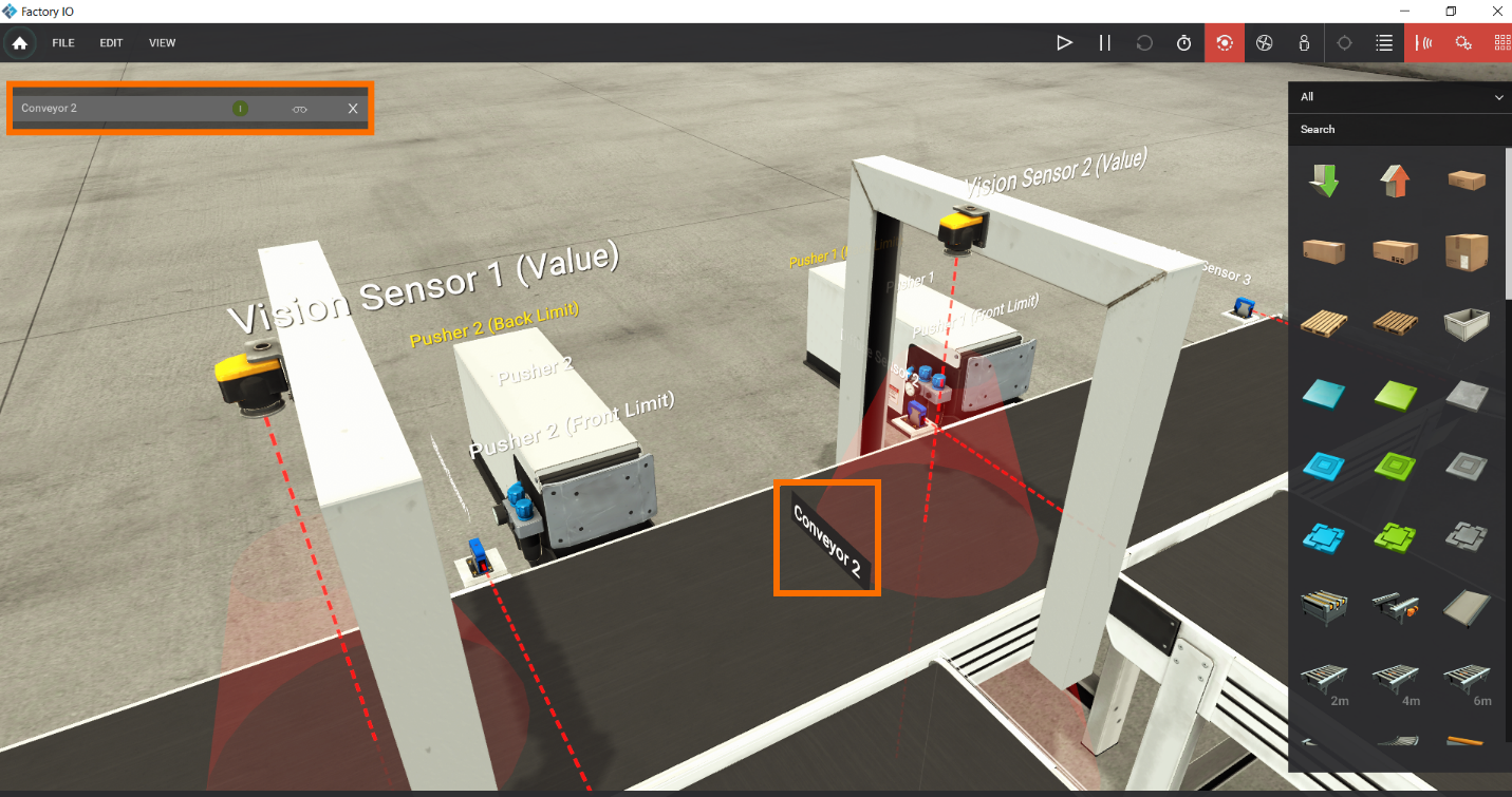
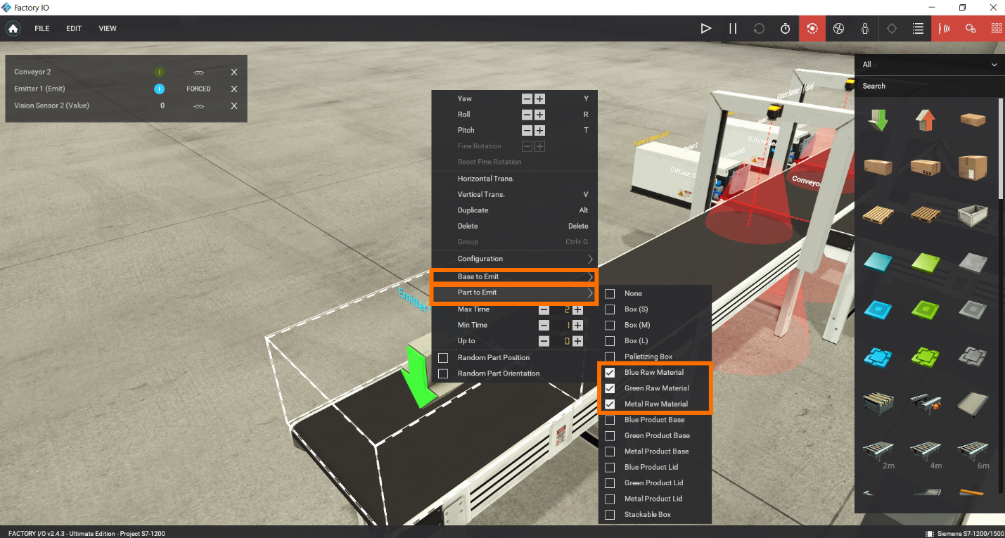
Now let’s see the configurations of “Emitter,” “Vision Sensor,” and “Digital Display.”
Step 1.2:
First, For “Emitter,” make “Base to Emit” to “None” and “part to emit “to this configuration.
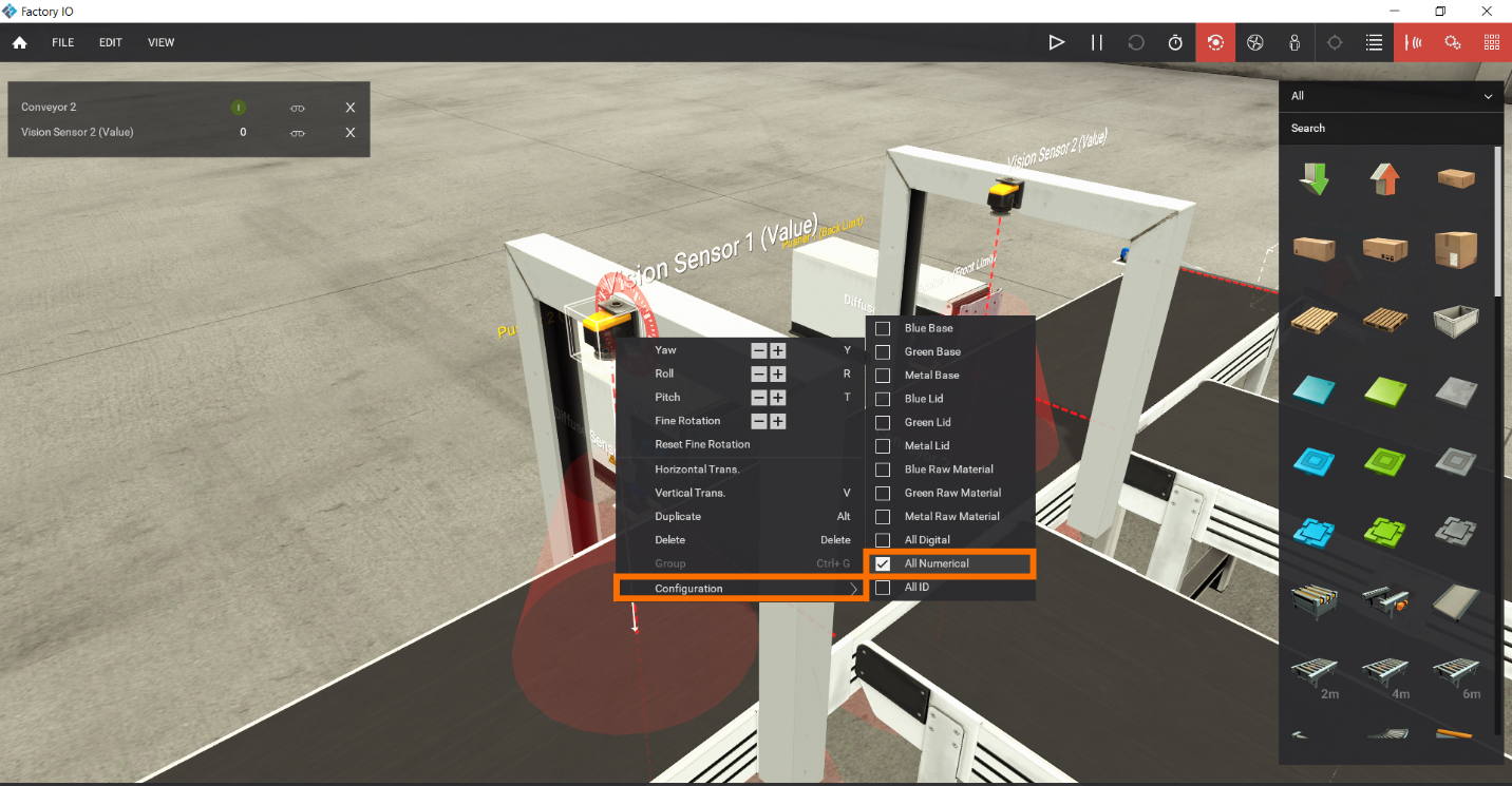
Now, for two “Vision Sensors,” Right click and go to its configuration, and select “All Numerical.”
This option provides distinct values for each color. When the “Vision Sensor” detects “Blue material,” it will return the value “1.” Similarly, “Green Material” will return the value “4,” while “Metal Material” will result in a matter of “7.”
Note: we can use only one “Vision Sensor” for this project, but having two will make it simpler to learn and follow along with the programming.
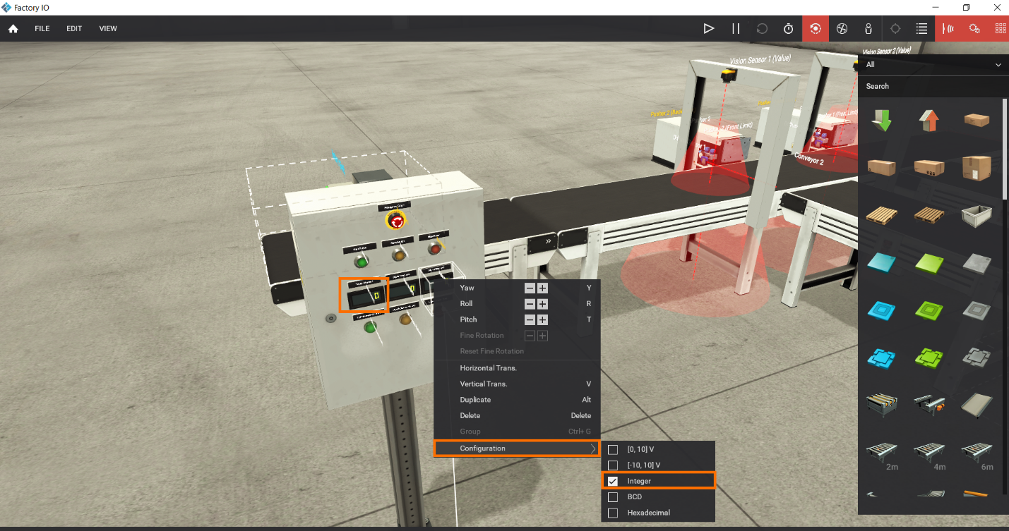
Now, For “Digital Display,” make its “Configurations" to “Integer.”
Step 2 – configure inputs and outputs
Step 2.1:
Click on “File,” then Select “Driver.”
Select your PLC; in this case, we will select “Siemens S7-1200 /1500”.
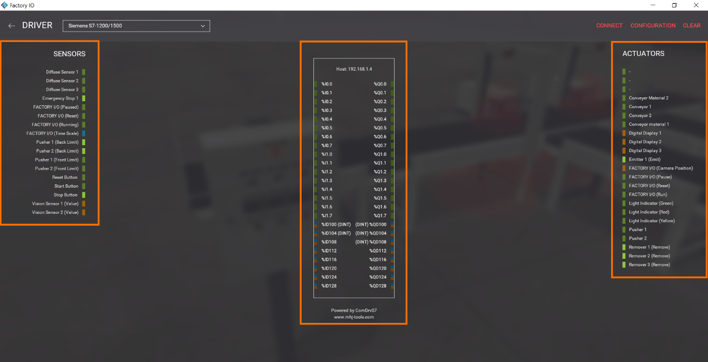
Step 2.2:
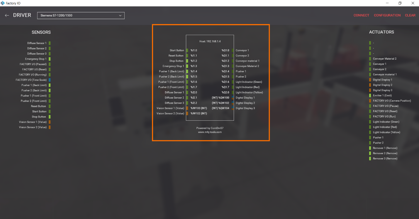
Assign all the inputs and outputs to the appropriate addresses by dragging and dropping them to their addresses.
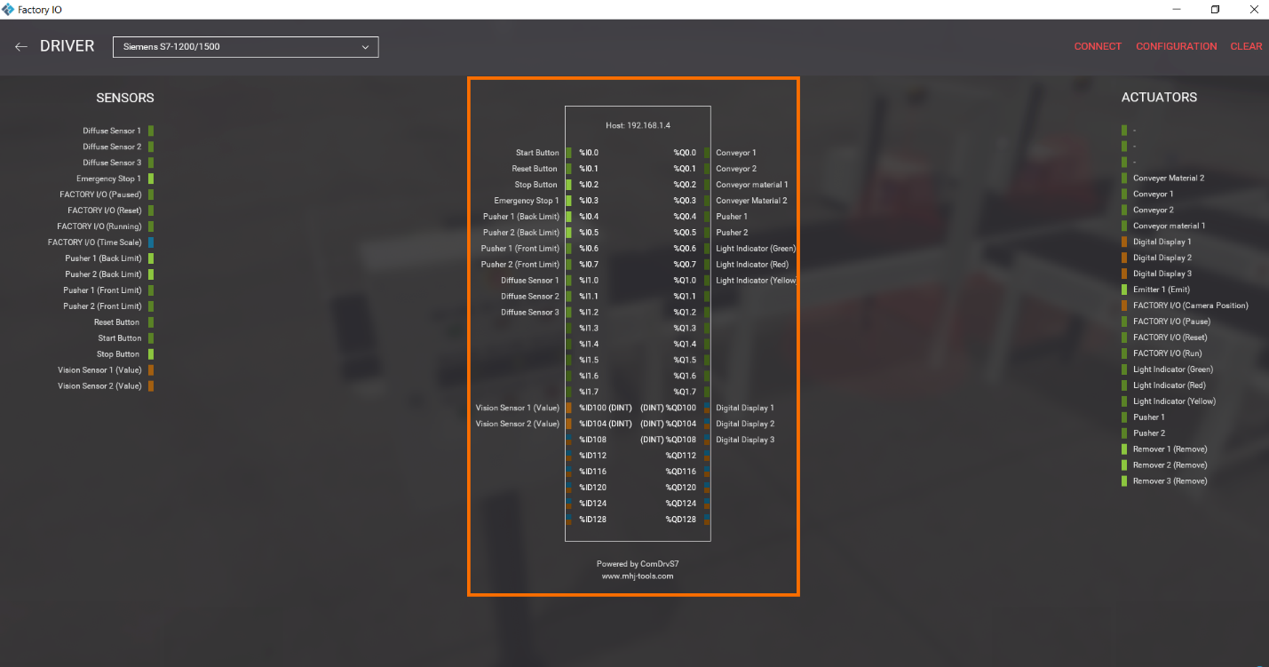
Note: the addressing of inputs and outputs in the simulation must be distinct from the actual hardware addresses. Therefore, let's proceed to modify them.
Step 2.3:
Click on “CONFIGURATION.”
Within the “I/O Points” section, we can define the offset and count. In this case, we're dealing with 11 digital input signals, nine digital output signals, two analog input signals, and three analog output signals. Let's set the offset to 1 for both input and output signals. Within the “I/O Config” section, select analog signals to be “WORD,” not “DWORD.” all counting will be “INT”; we don’t need to set them as “DWORD”.
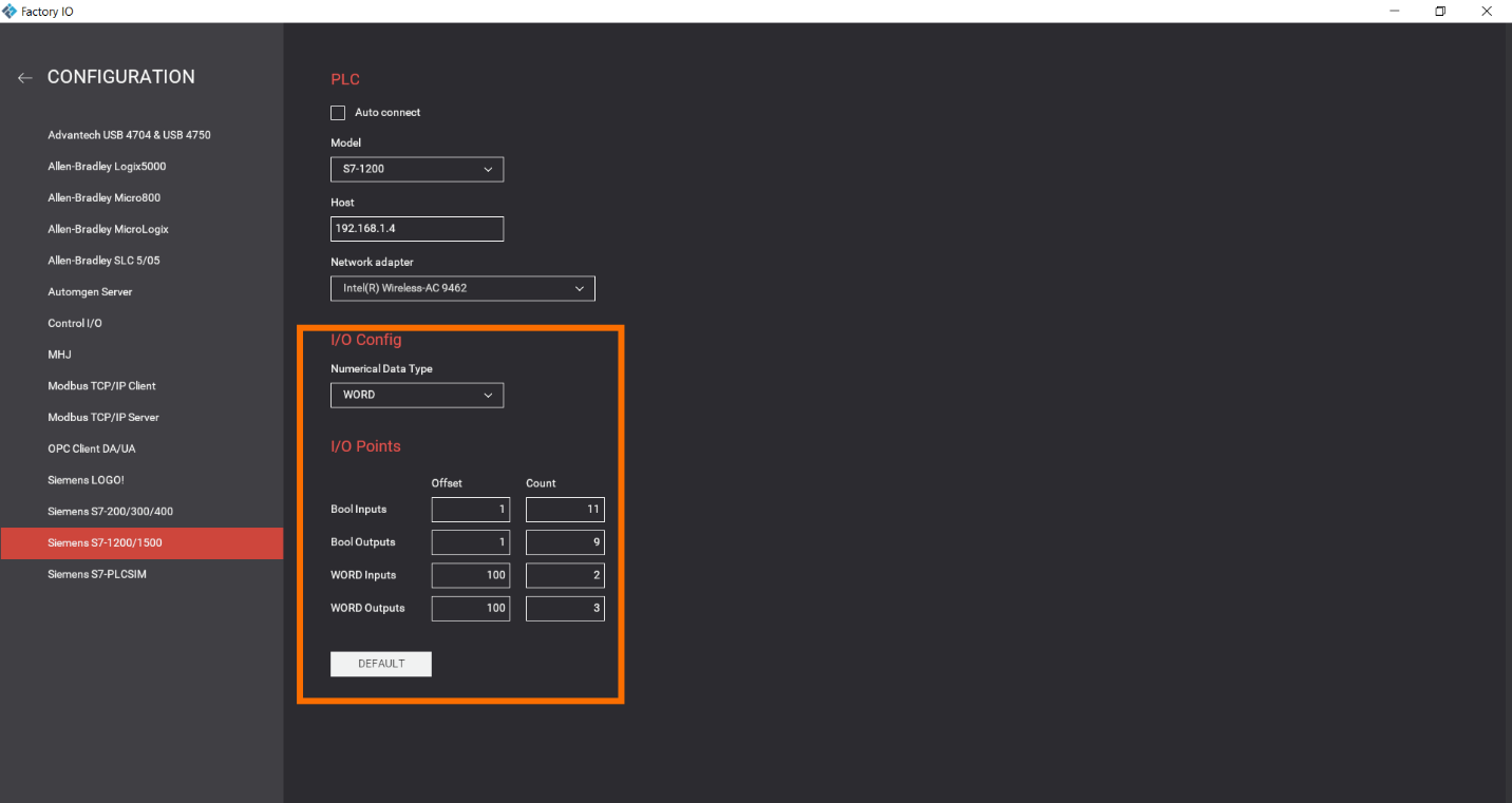
Now we are done.
Tia Portal side – Configurations
Let's initiate a New PLC project utilizing the S7-1200.
Step 1 - New TIA Portal Project
Step 1.1:
Begin by selecting "Create New Project." During this step, assign a distinctive name to your project to uniquely identify it within the system. Then Click on “Create.”
Step 1.2:
Select “Configure a device.” Then Select “Add new device.”
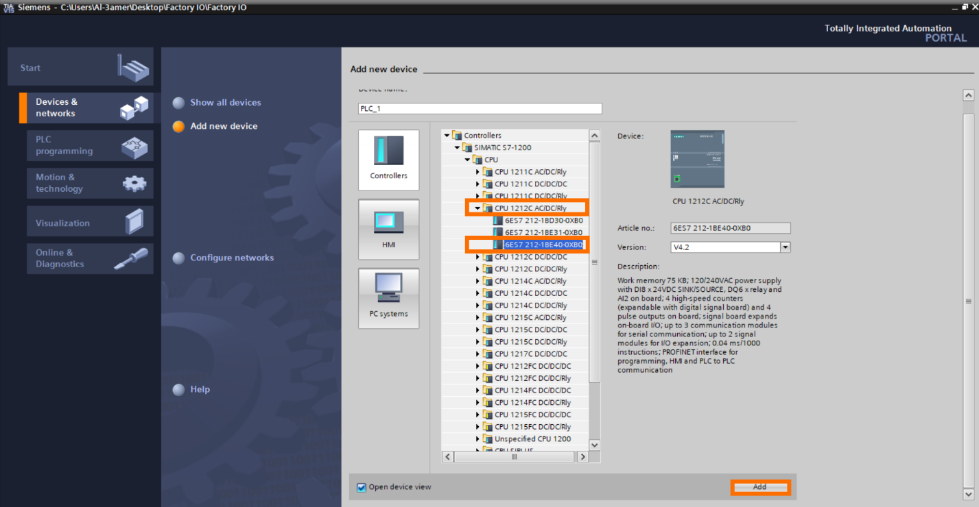
Step 1.3:
Select your PLC. In this tutorial, let’s use “S7-1200 CPU model 1212C AC/DC/Rly” with the part number “6ES7-212-1BE40-0XB0.” Please choose the PLC that matches your setup. Then Click “Add.”
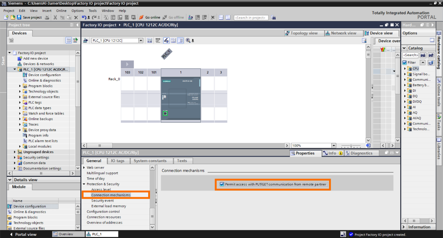
Step 2 – PLC Hardware Configuration
In PLC hardware configurations from “Connection mechanism” active “PUT/GET.”
Step 3 – PLC Program
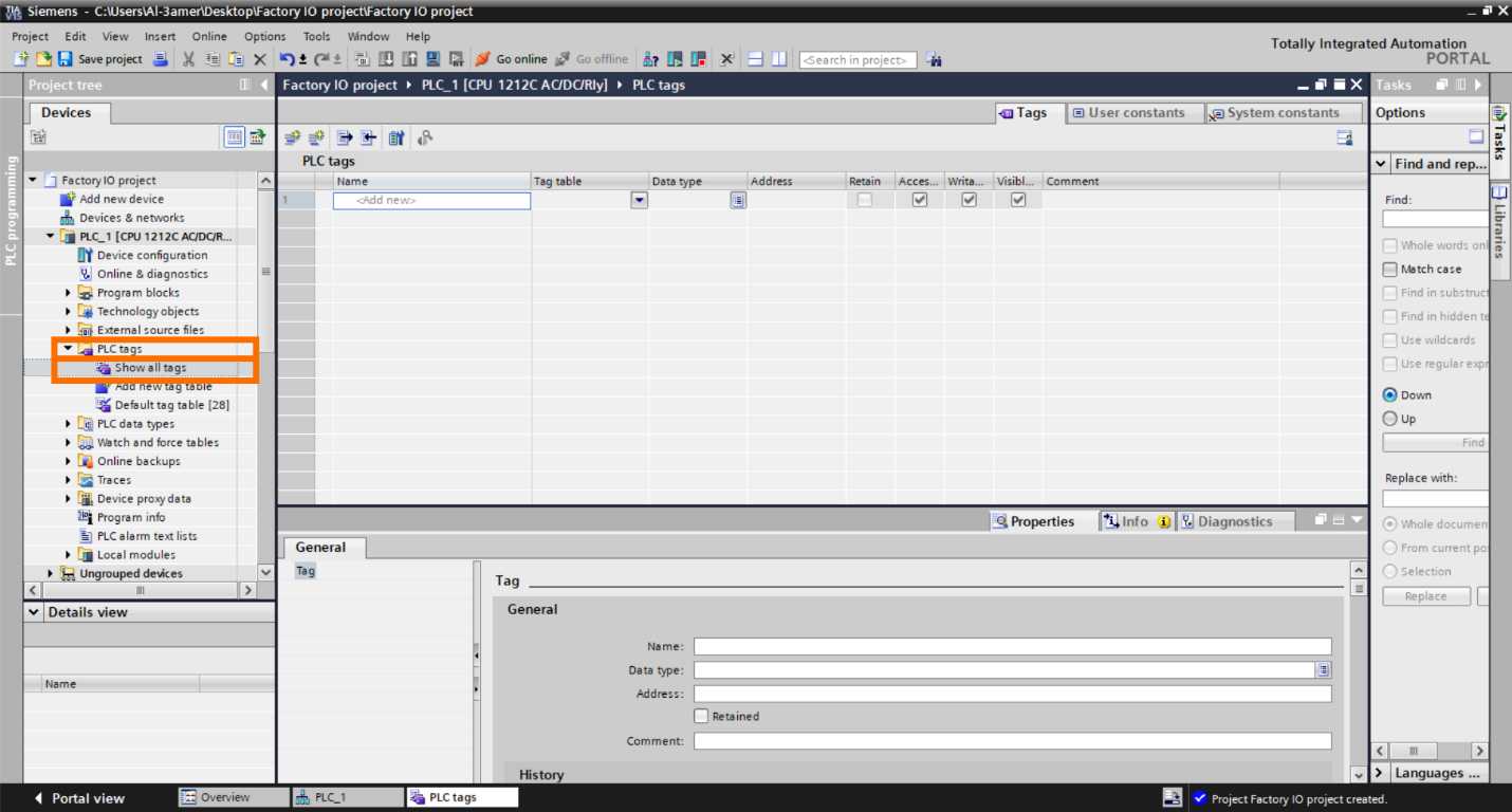
Step 3.1:
Go to “PLC tags,” then click "Show All tags.”
Step 3.2:
In the “PLC Tags” interface, include all your inputs and outputs from “Factory IO.”
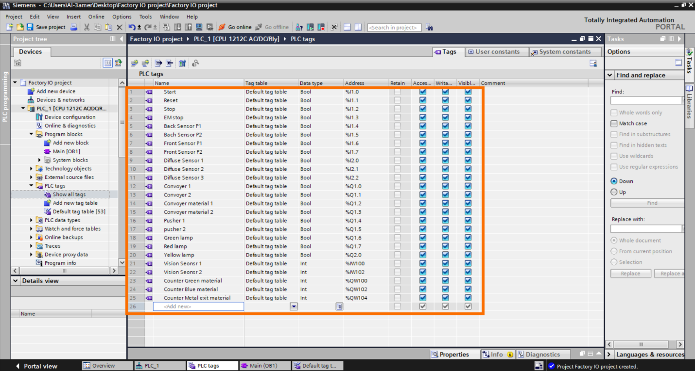
Currently, all tag addresses in the PLC correspond to the same addresses in Factory IO.
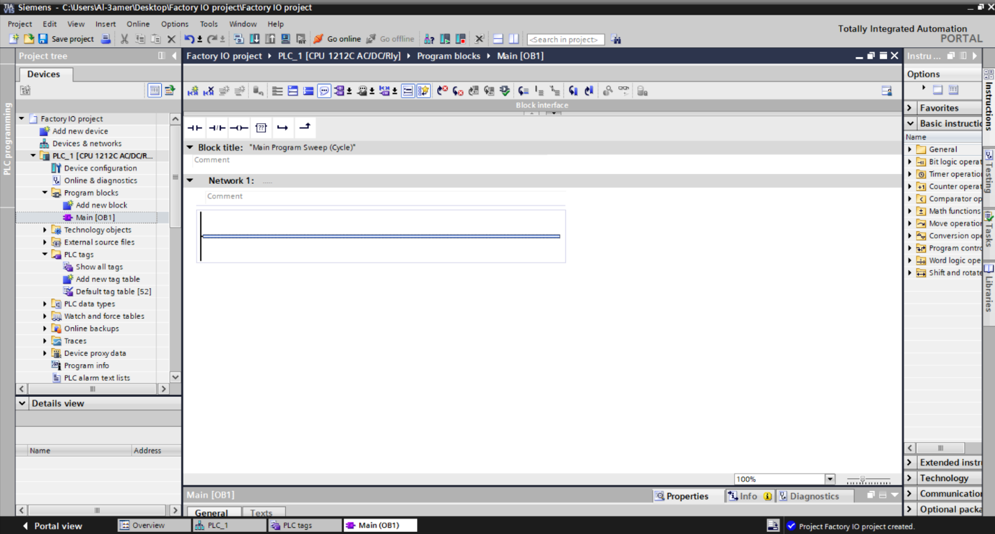
Step 3.3:
Now go to “Program blocks” then click “main [OB1]” to start writing the PLC program. We will use “Ladder Diagram programming.”
Step 3.4:
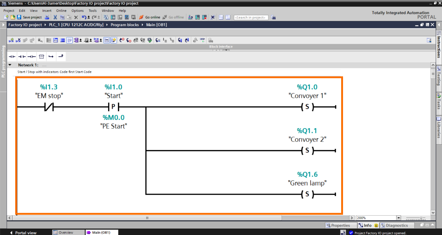
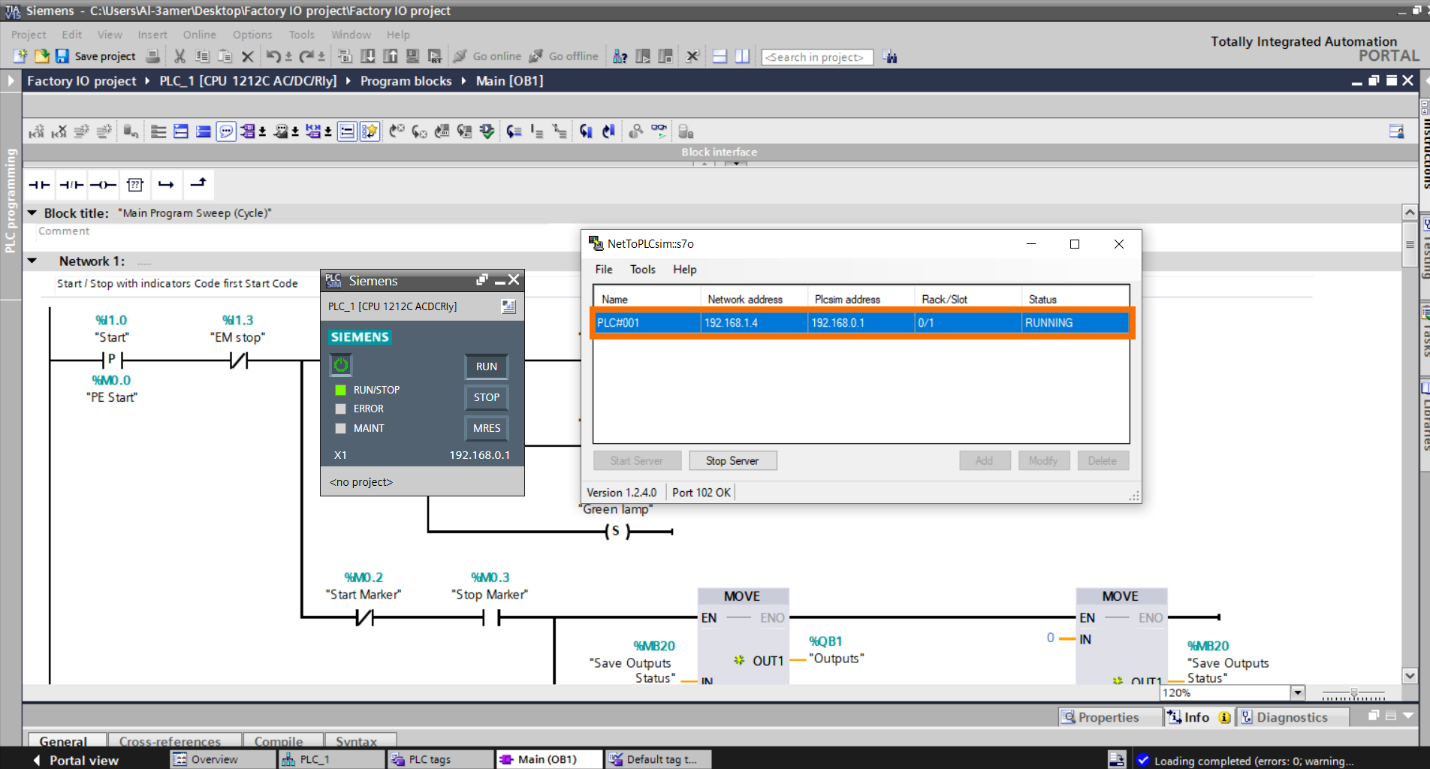
Let's begin with the programming for “Start” and “Stop” with indicators.
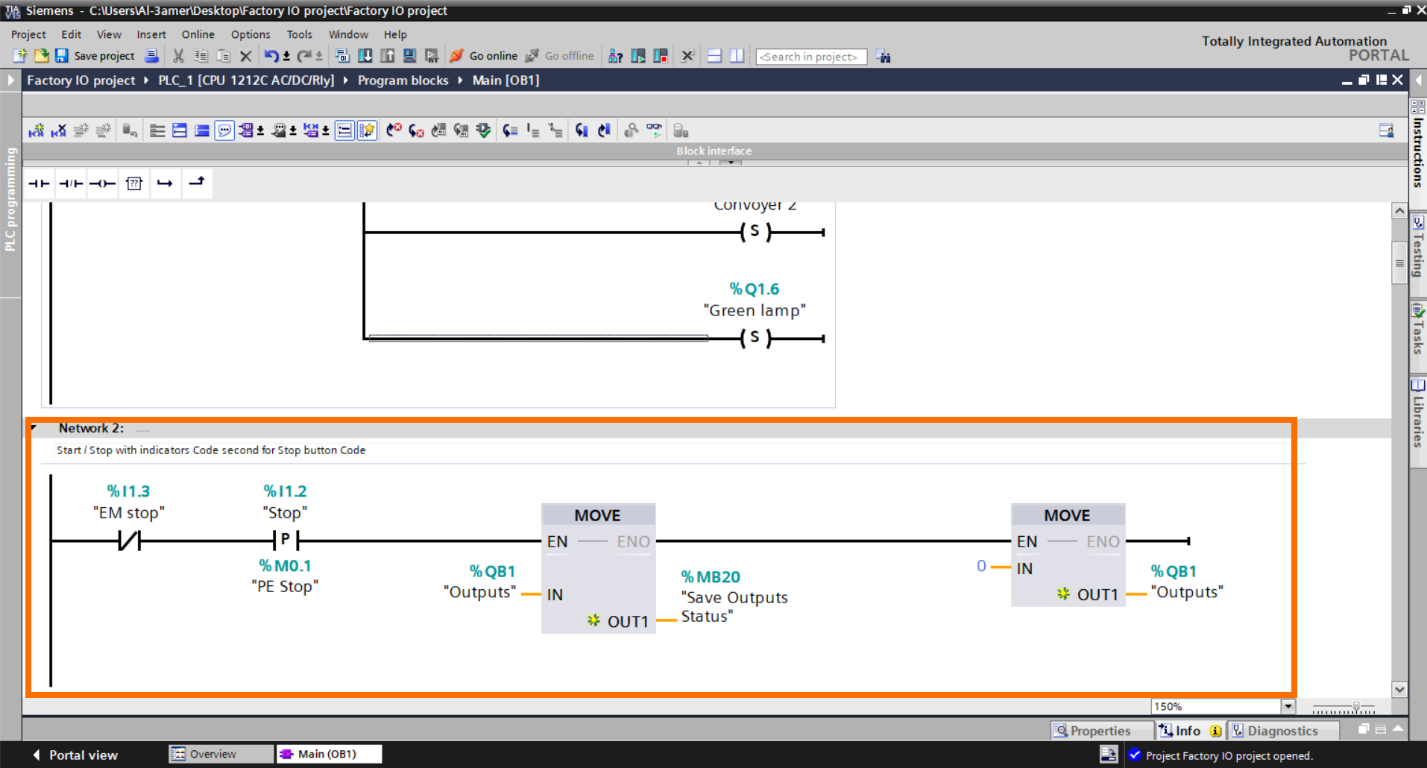
Now, we want to preserve the status of all actuators in the system. This is crucial because when we stop the system, we don't want to restart everything from scratch. Instead, we want the active outputs before the system was stopped to return to their previous state. These lines of code store and restore the status of these outputs.
So let’s make this: when the "Stop" button is pressed, the system captures the status of "Outputs QB1" and transfers this status to "MB20." Then move “0” to all outputs. This step is crucial for saving the current state of the outputs before stopping the system.
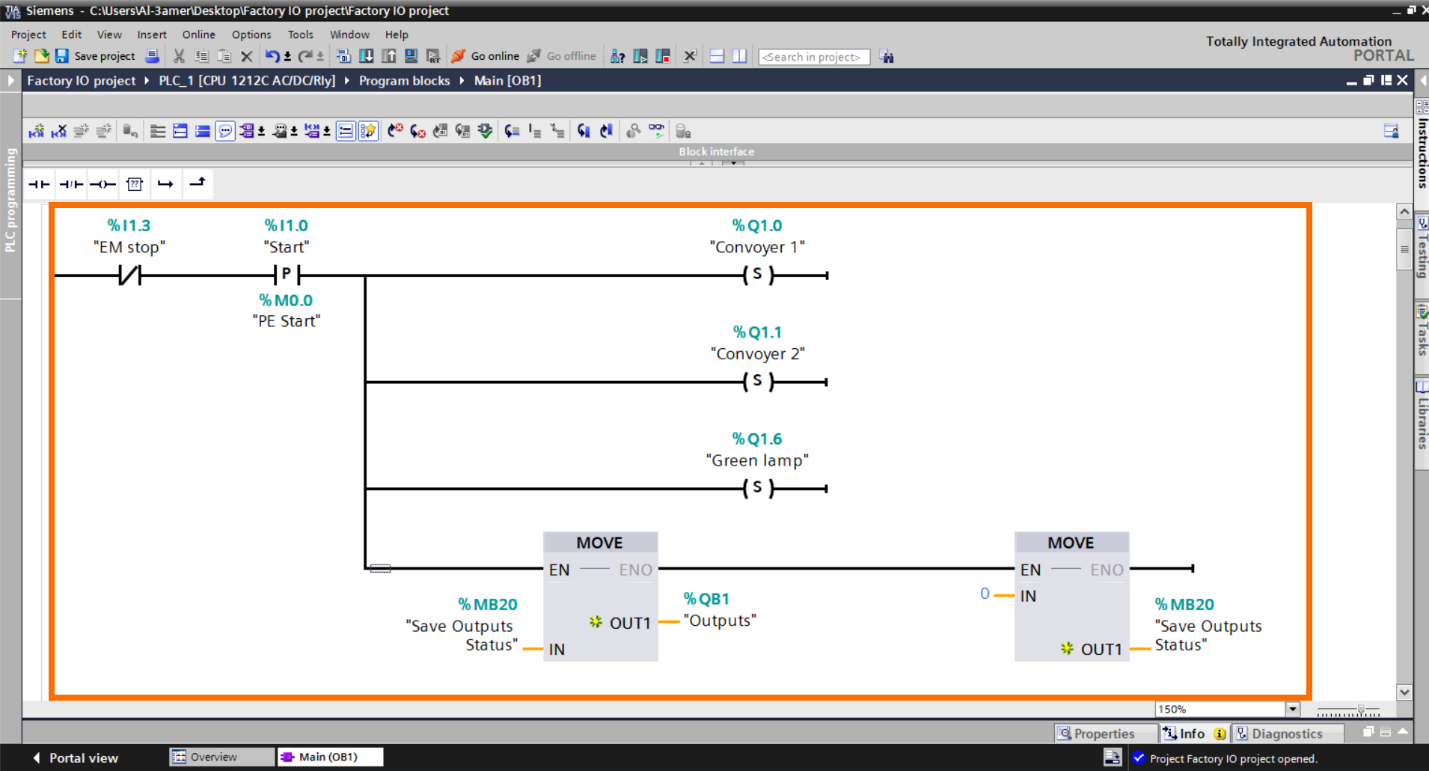
Now we want when the "Start" button is pressed again after pressing the “Stop” button, the system retrieves the saved status from "MB20" and assigns it to "Outputs QB1," effectively restoring the outputs to their previous state.
Then The "0" value is moved to "MB20" to reset all saved statuses, ensuring that when the "Stop" button is pressed again, the system begins with a clean slate.
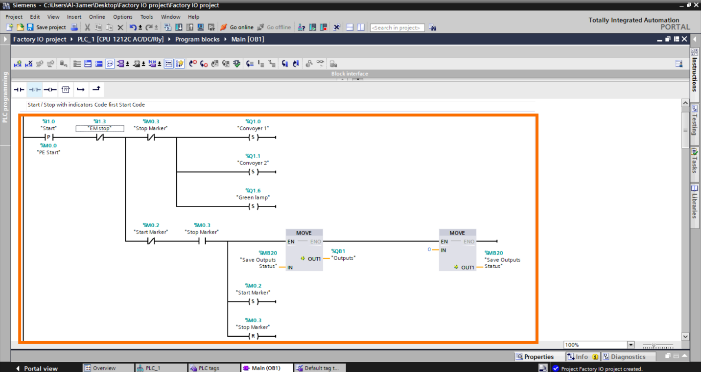
Now, we will use two markers, "Start Marker" and "Stop Marker," to serve the purpose of preventing duplicate data transfer. In the "Stop" condition, they ensure that values are only moved once to "MB20," and in the "Start" condition, they make sure that values are not retrieved more than once from "MB20." This helps maintain efficient and accurate data handling. Also, we will use “Stop Marker” to indicate that the system is in the first Run state or that the “Stop” button is pressed.
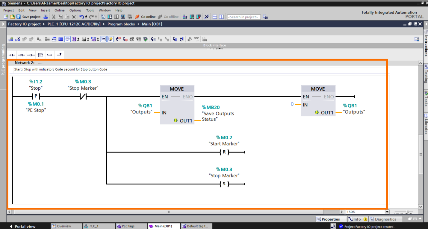
Note: The first Line in the “Start Button” Code is the initial startup of the system “First Run State.” Since no one has pressed the "Stop" button, we initiate the system to run “Conveyor1, Conveyor2, and the Green lamp.” This setup ensures that these operate when the system starts.
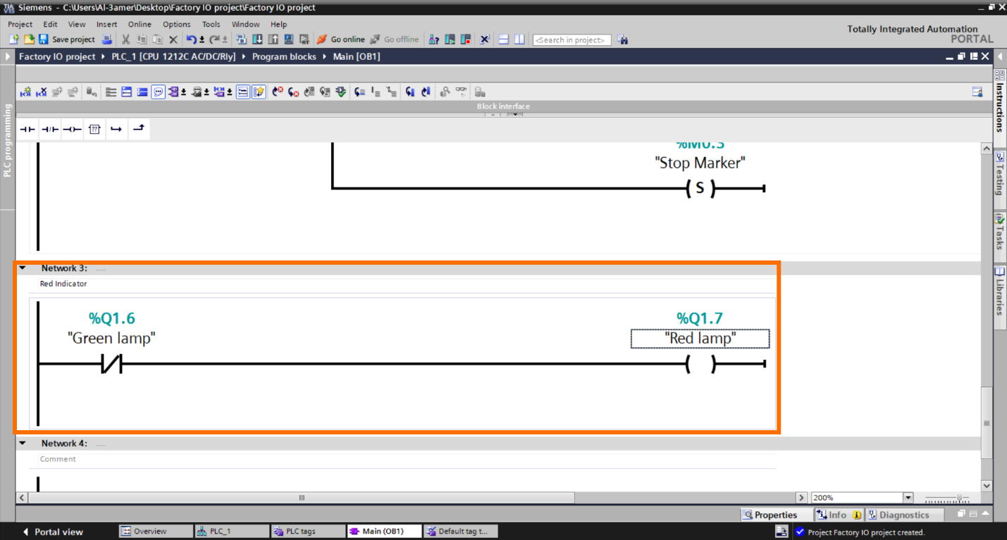
Now let’s see the code For “Red lamp indicator.” we will make a simple code while “Green Lamp” is not active, then active “Red lamp indicator.”
Step 3.5:
Let’s Write the “Vision Sensor” Code now.
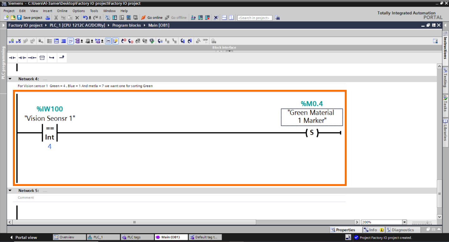
In the figure above, it’s a code for the first “Vision Sensor.” When this sensor detects a "Green material," which we want to sort, it sets a "Marker.”
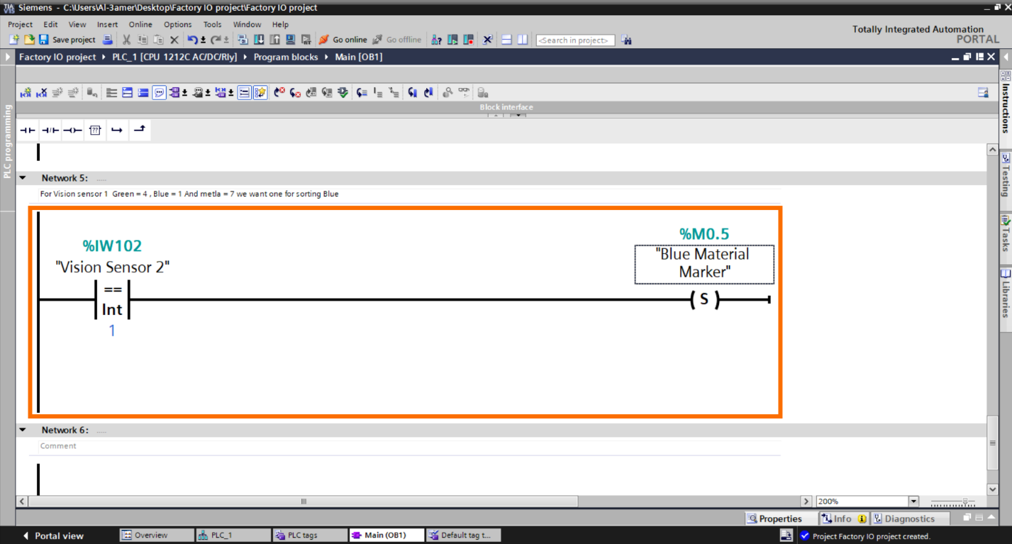
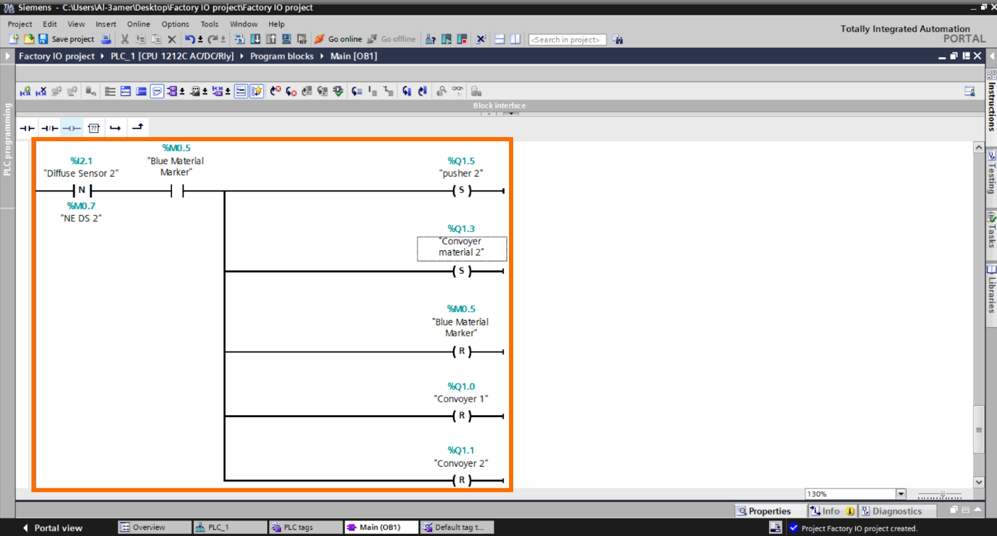
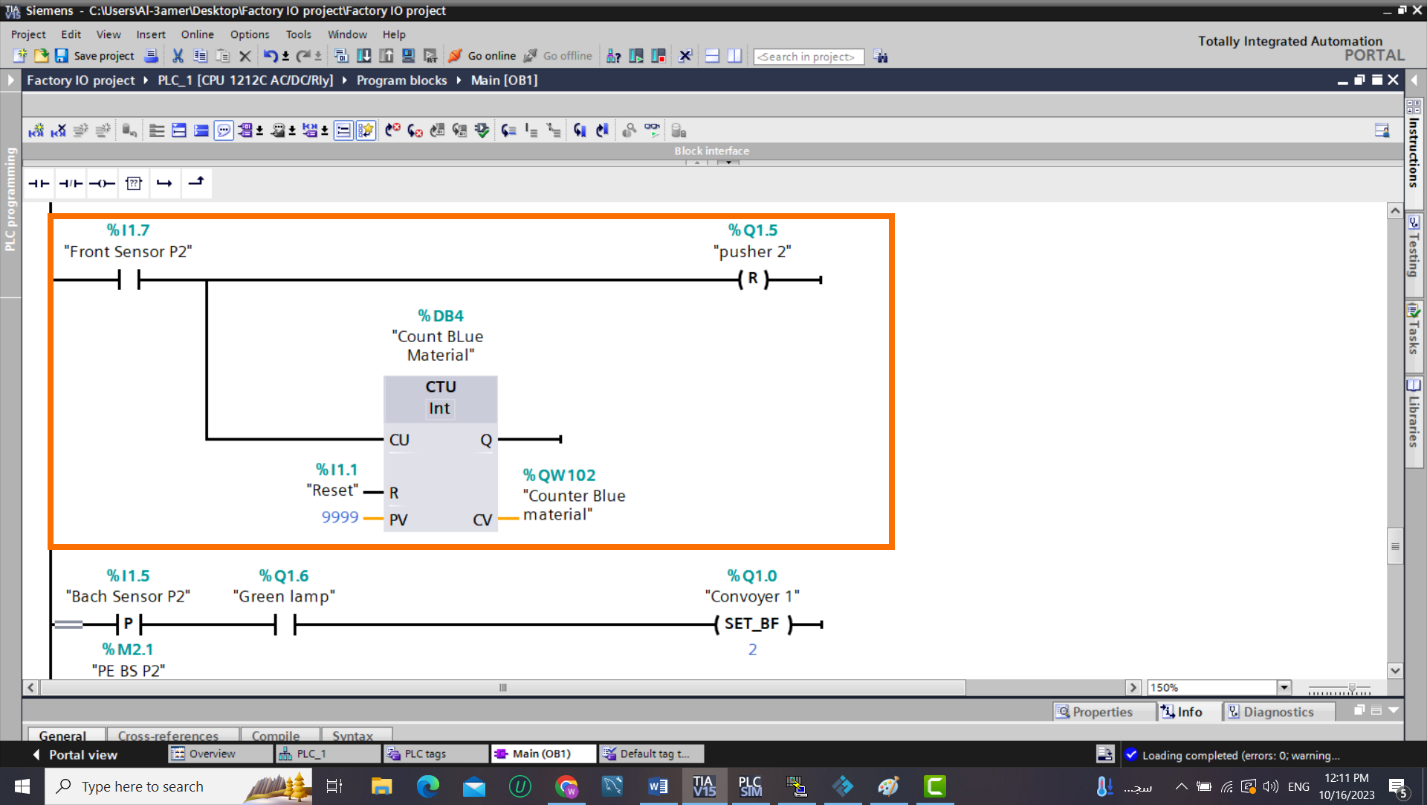
Now let’s make the same for the second “Vision Sensor.” for sorting “BLUE material.”
Step 3.6:
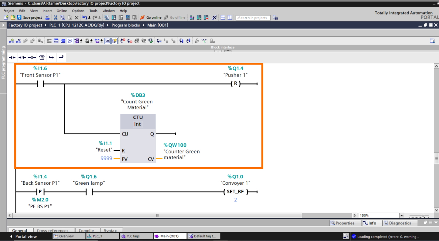
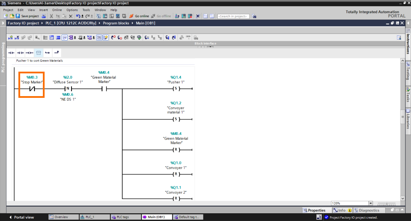
Let’s Write the “Pusher” Code.
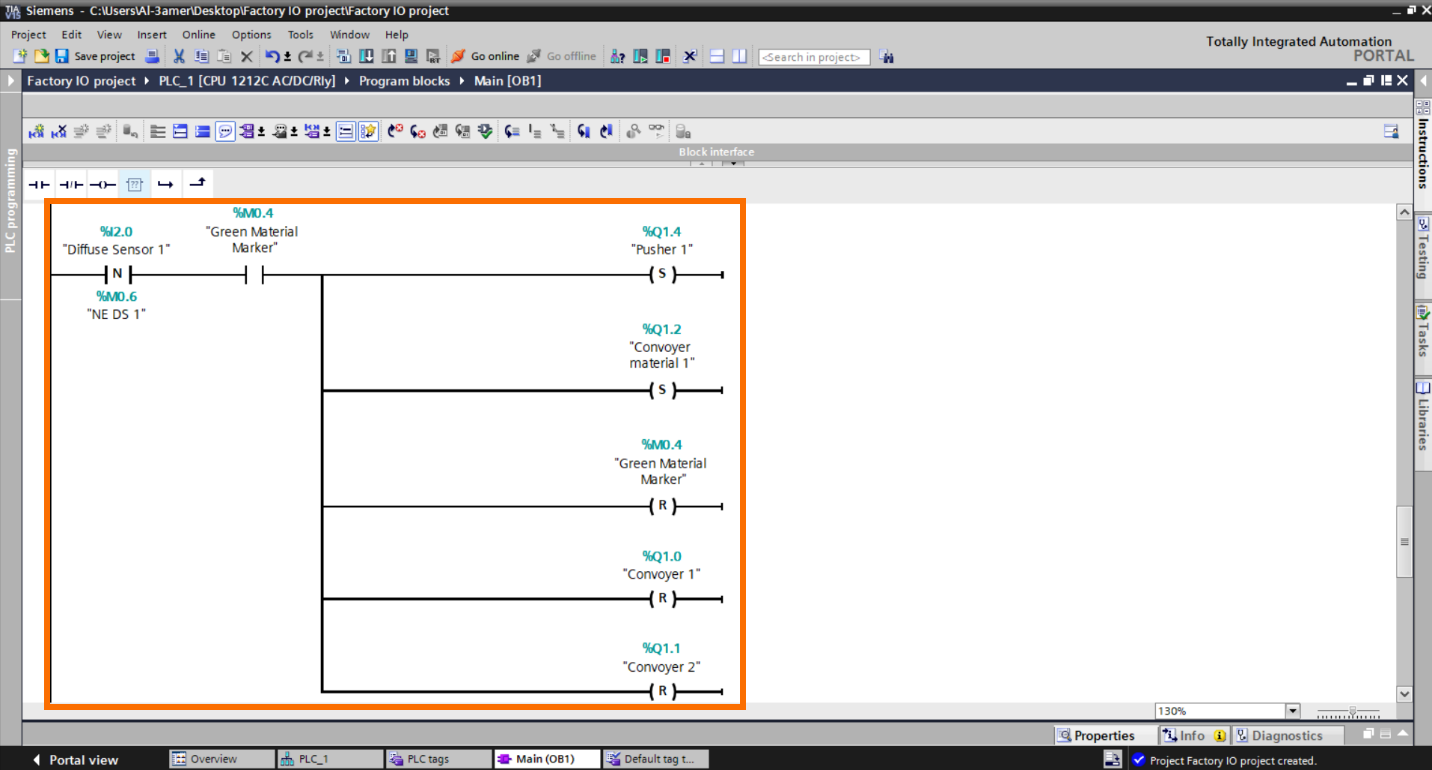
In the figure above, it’s a code for the first “Pusher” with the negative edge of the First “Diffuse Sensor.” if the material is “Green,” the “Pusher” will set to on with “Conveyor Material1” and reset the marker of “Green Material” for the following material, also reset “Convoyer1” and “Convoyer2” during pushing material process. Let’s do the same with the second “pusher”.
Note: we don't have a specific indication to confirm whether the sorted material has exited the conveyor or not. Therefore, we will set the conveyors to an "on" state but not reset them. To address this, we can implement a timer to reset the conveyors after a certain period or use sensors at the exit points for more precise indication.
Now, let's proceed with the programming to set "Conveyor1" and "Conveyor2" back to their operational state after the pushing process is completed.
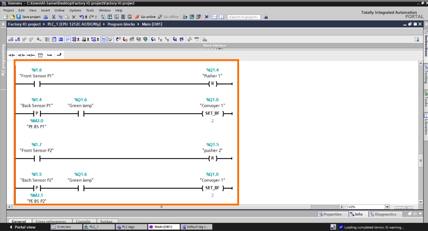
In the figure above, we reset “Pusher” when it reaches the "front limit sensor," then wait for the "Pusher" to return to its "back limit sensor" set again "Conveyor1" and "Conveyor2" to “ON” state. This identical process is applied to both "Pushers" in the system. The “Green Lamp” to make sure “Convoyer1 and Convoyer2” will not be active in the “stop” system state.
Step 3.7:
Let's write the program of counting the materials.
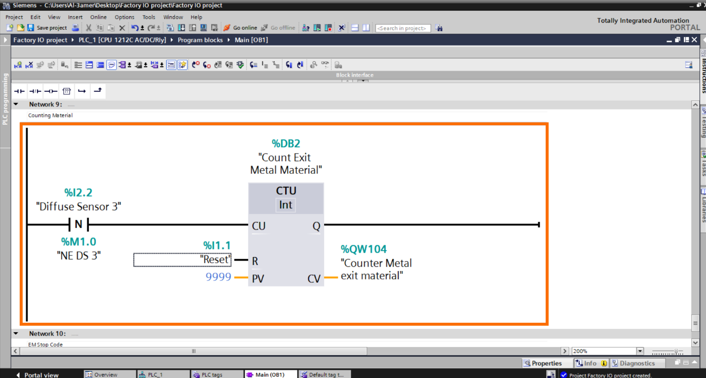
In the figure above, we are now implementing a count for the "Exit Metal Material." While it's possible to count the two sorted metal materials separately in their respective networks, we are opting to count them when each "Pusher" reaches its "front Limit sensor”.| Note, we used the “Reset button” to reset the counter.
Step 3.8:
Now, let’s write the “EM Stop “code.
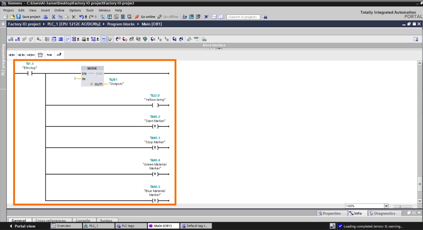
In the figure above, we reset all to initiate the system from the beginning later.
Step 3.9:
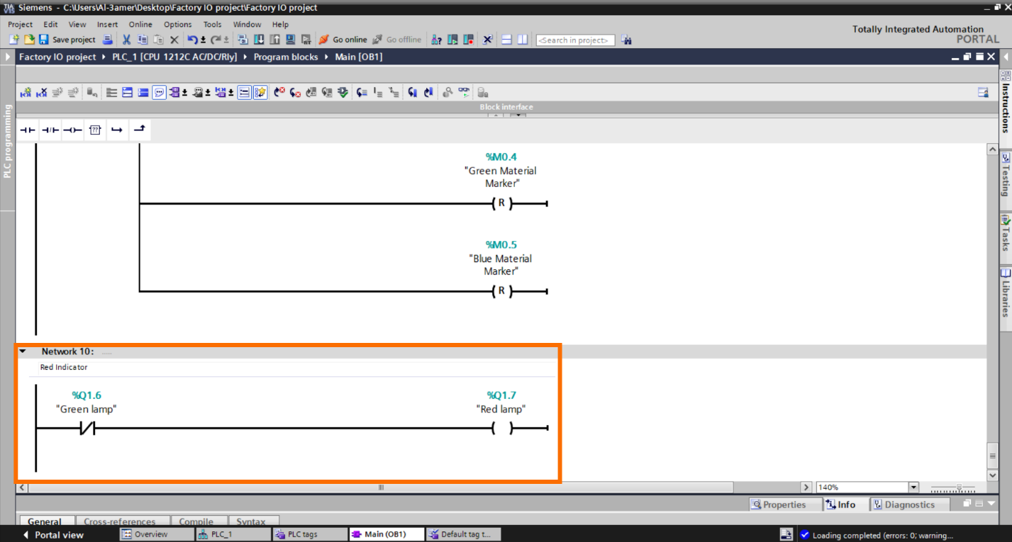
We'll make a modification to the "Red indicator" network by placing it as the final network in the program, because the "EM stop" network resets the "Red lamp." Consequently, in the subsequent network where the "Green indicator" is not active, the "Red lamp" will be activated at the end of the "Scan Cycle."
Step 3.10:
To increase the system’s reliability, we will place a "Stop Marker" to all networks to ensure that no outputs will activate in the "Stop" system condition.
Add it to all networks. |Note, it’s not required really but we add it to make sure no outputs will be run if its condition is true in the “Stop” system state.
After writing the program, Run “Simulation.” Note| This option is only if you don’t have a real PLC.
Net-To-PLC-sim side [Optional] – Configurations
Execute "Net to PLCSim" and establish a network connection between your PLC and your PC using their IP addresses. If you are unsure about how to configure these settings, you'll find a detailed, step by step guide in the “Net To PLCSim Side Configuration” section of this tutorial.
Factory IO side – Connection
Step 1 – Configure connection settings
Step 1.1:
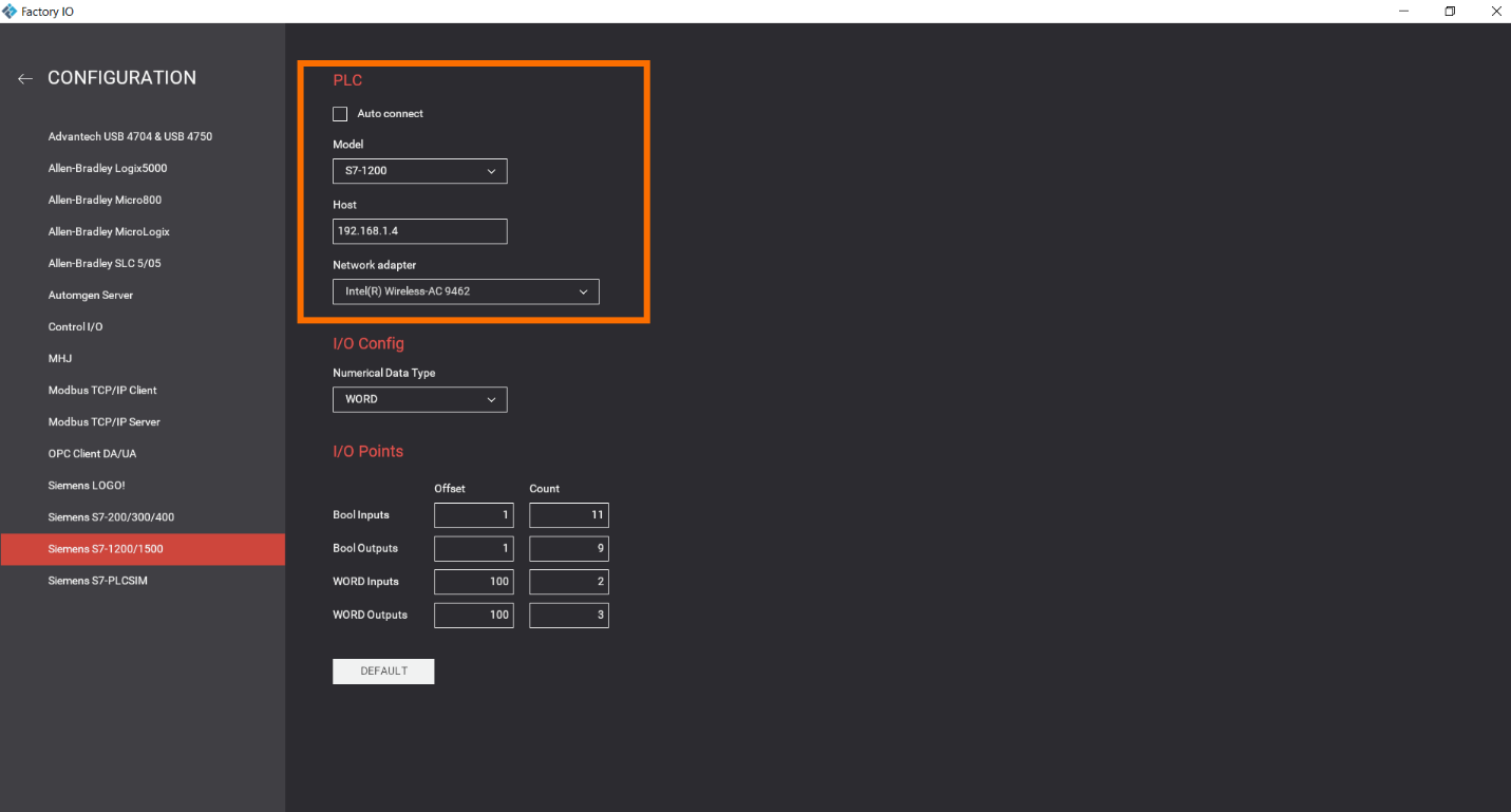
Within the drive interface, click on “Configuration.”
Choose your “model,” specify the “PLC-IP,” and select the appropriate “network adapter.” Since we are simulating a real PLC on the PC network, set the host as the IP address of the PC network, and choose the network adapter corresponding to your PC network, which in this case is “Intel Wireless AC 9462.”
Step 1.2:
Return to the driver's interface and click “Connect.” and it will be connected.
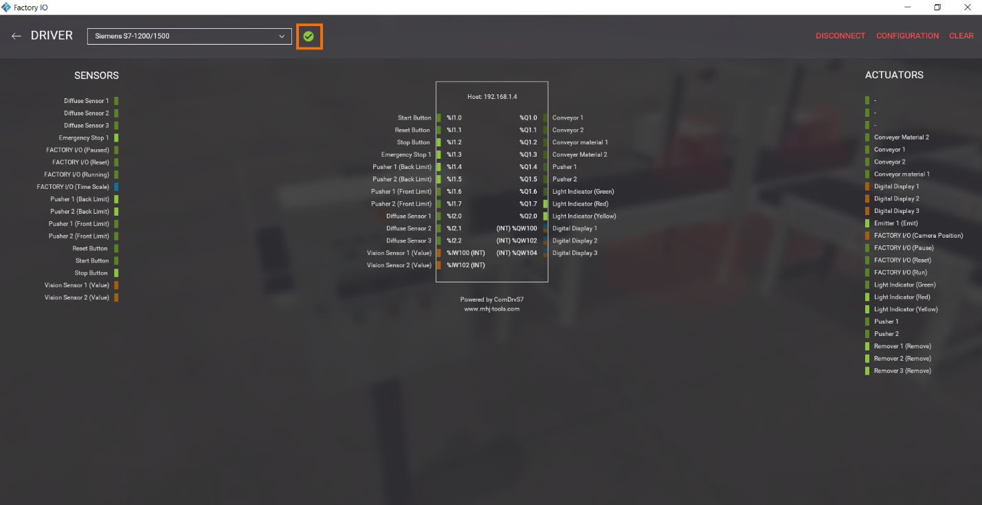
Now return and run the scene.
System Overview and Project Files
All the necessary files and a video demonstration of the running system are available here.
Conclusion
In this guide, we've covered various topics, from configuring Factory IO and creating a color-based sorting project with material counting to writing PLC code for different system functions. The synergy between Factory IO and TIA Portal has enabled us to design, simulate, and program a fully operational control system.
By following this tutorial, you've gained a practical understanding of how to integrate these two powerful tools, laying the groundwork for more advanced automation projects in the future. As you continue your journey in industrial automation, remember that this is just the starting point, with numerous exciting possibilities on the horizon. Whether you're a newcomer or an experienced programmer, this tutorial provides a solid foundation to expand your knowledge and explore the limitless potential of industrial automation.