First look at Schneider Electric’s Machine Expert Software

Introduction
Schneider Electric's Machine Expert stands as a robust software solution tailored for automation engineers and PLC (Programmable Logic Controller) programmers, providing an integrated platform for the configuration and programming of Schneider’s industrial control systems. Widely embraced in manufacturing and process industries, Machine Expert serves as a centralized hub for creating, managing, and optimizing automation projects. Throughout this guide, we will offer a comprehensive overview of Machine Expert, delving into its functionalities and guiding you through essential steps to efficiently create and configure projects. We'll explore the software's key features, enabling you to harness its capabilities for streamlined and effective automation processes.
In this tutorial, you'll embark on your initial steps into Schneider Electric's Machine Expert, gaining insights into project creation and configuration. Beginning with the basics, we'll guide you through the process of initiating a new project, selecting the appropriate controller model, and defining crucial project parameters. As your project takes shape, we'll navigate through Machine Expert's main interface and its fundamental sections. Essential tools and features will be covered; we'll explore the Device Tree, a crucial space for configuring hardware-related settings such as digital inputs and outputs, extension modules, and communication interfaces. The tutorial will conclude with a detailed examination of the Application Tree, focusing on Global Variable Lists (GVL), PLC tasks, and Program Organization Units (POUs).
Prerequisites
To follow along this tutorial, you will need an installation of Schneider Electric’s Machine Expert. We recommend that you follow the “How to download and install Schneider’s Machine Expert” tutorial beforehand.
Creating a project in Machine Expert
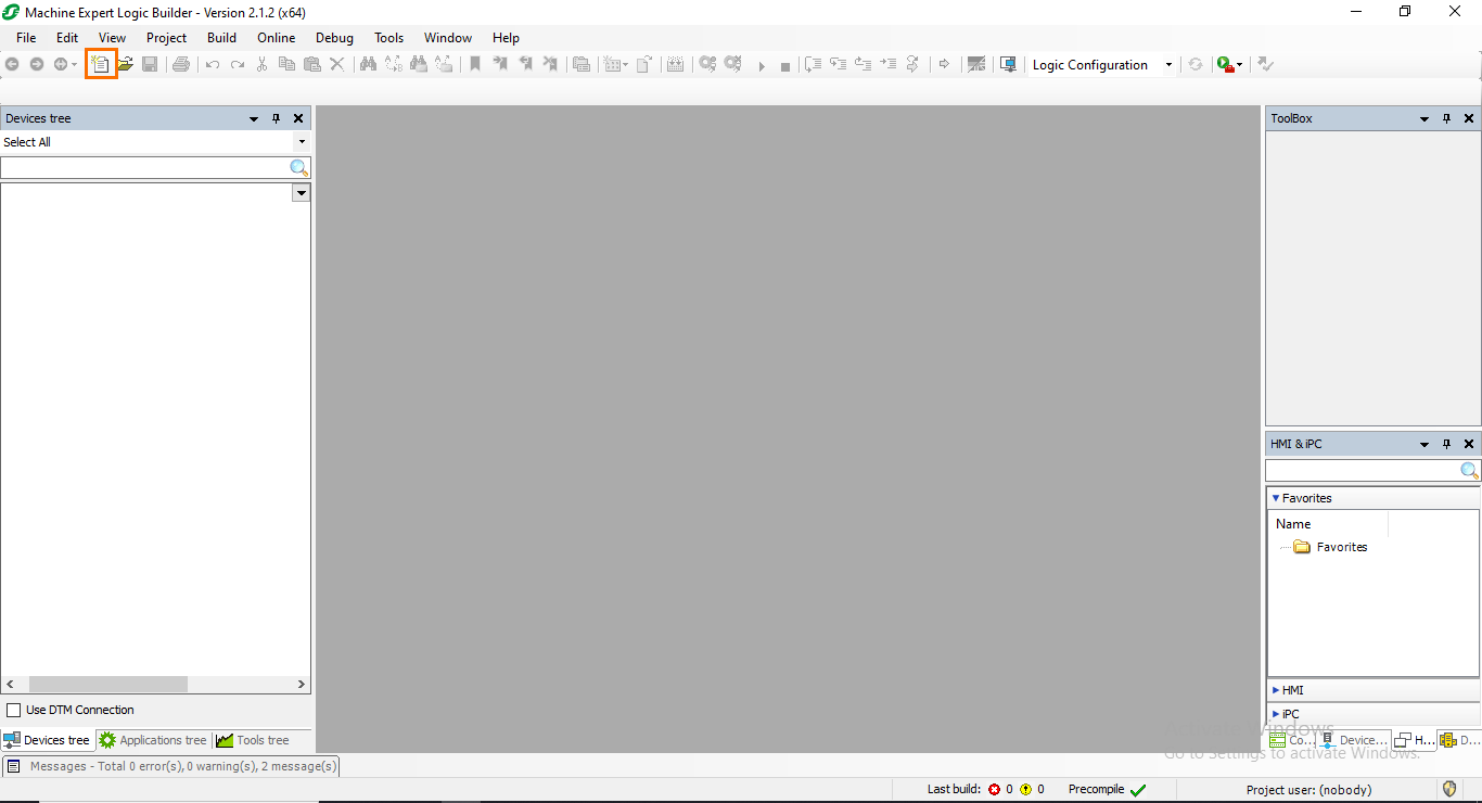
Let’s start by taking a look at how to create a project in Machine Expert. First, launch Machine Expert from your desktop or start menu. Once the loading is done, click on the “New Project” button. This can also be done by clicking on File -> New Project.
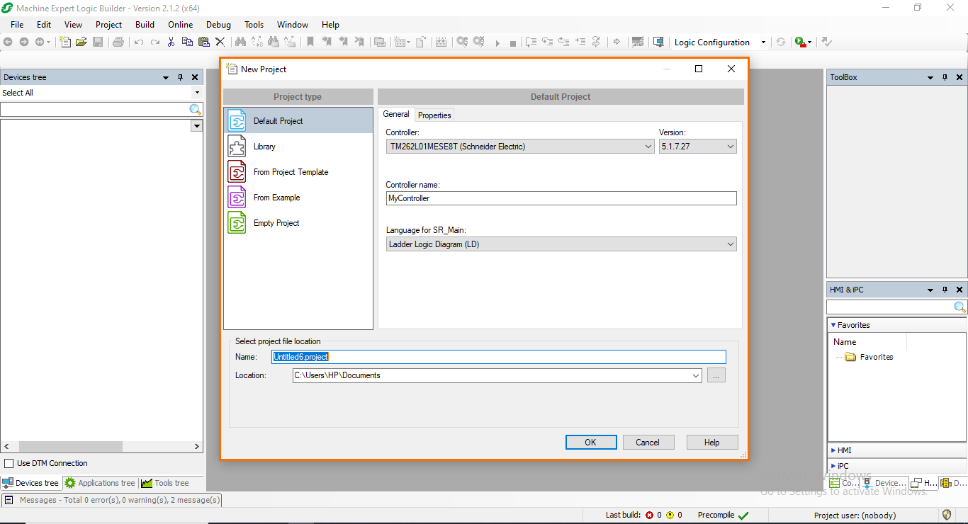
A small “New Project” window will open. Here, you can define the project type and configure it. Usually, you will mostly use the “Default Project” type. Note that it is also possible to create libraries, projects from templates, projects from examples, and empty projects.
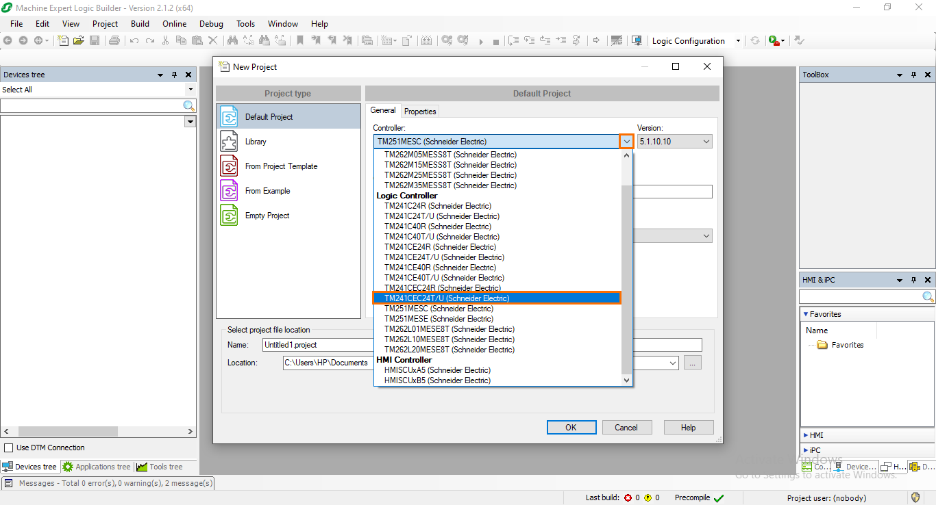
After selecting the project type, we need to select the controller model we will use in the project. For this example, we will select a TM241CEC24T/U. open the controller list and select the right model.
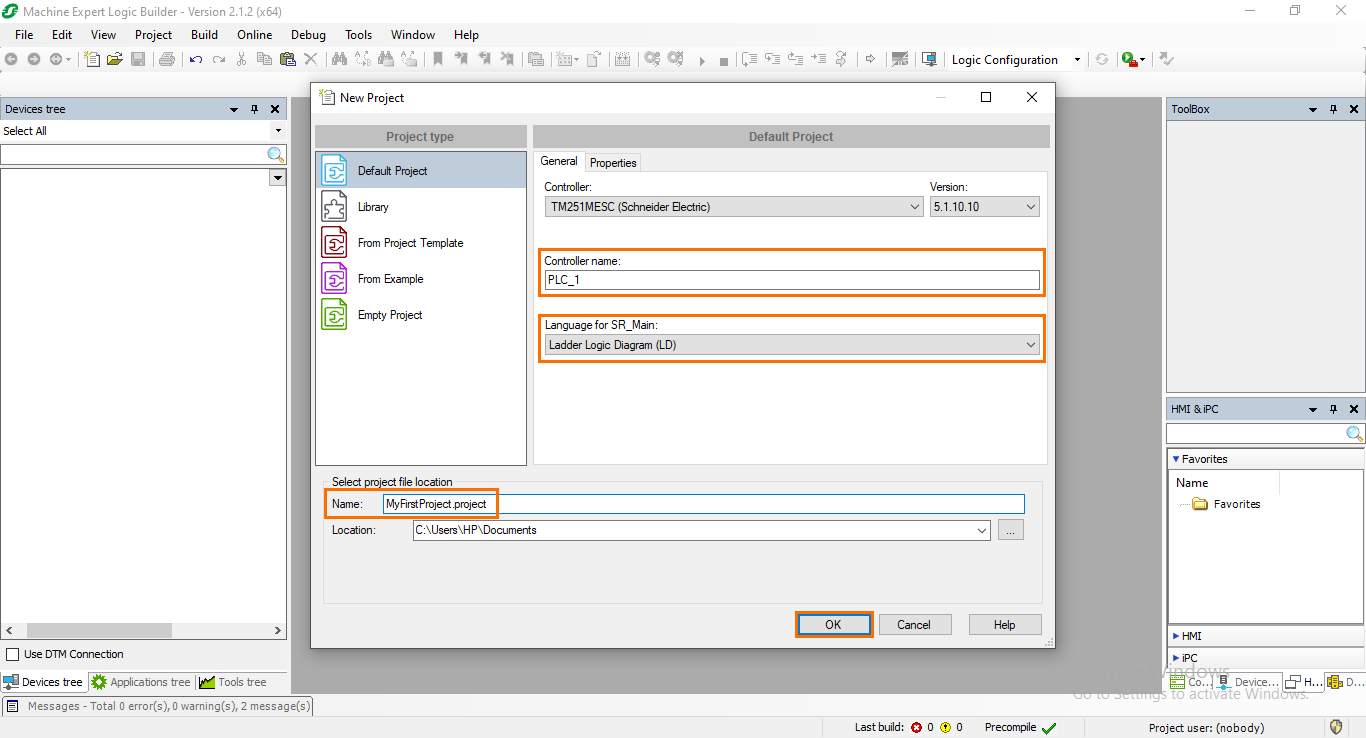
After that, we need to define the controller and project names. Also, you can select the default programming language for the project. For now, keep it at LD. Once everything is ready, click on OK.
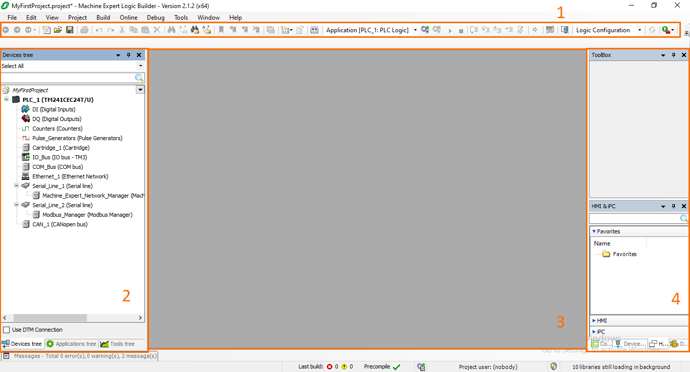
Once the project is created, you should end up using Machine Expert's main interface. It is mainly composed of four sections:
- Toolbar: Contains essential tools such as the new/open project buttons, save project, PLC login/logout…etc.
- Project trees: Here, you can navigate through the contents of your project. Everything is split into three tabs; Device tree for the hardware configurations, Application tree for your PLC program and software in general, and Tools tree for miscellaneous project tools such as libraries.
- Workspace: The actual field where all the configuring and programming are done.
- Toolbox: A set of tools and features that can be accessed quickly, such as instructions, devices…etc.
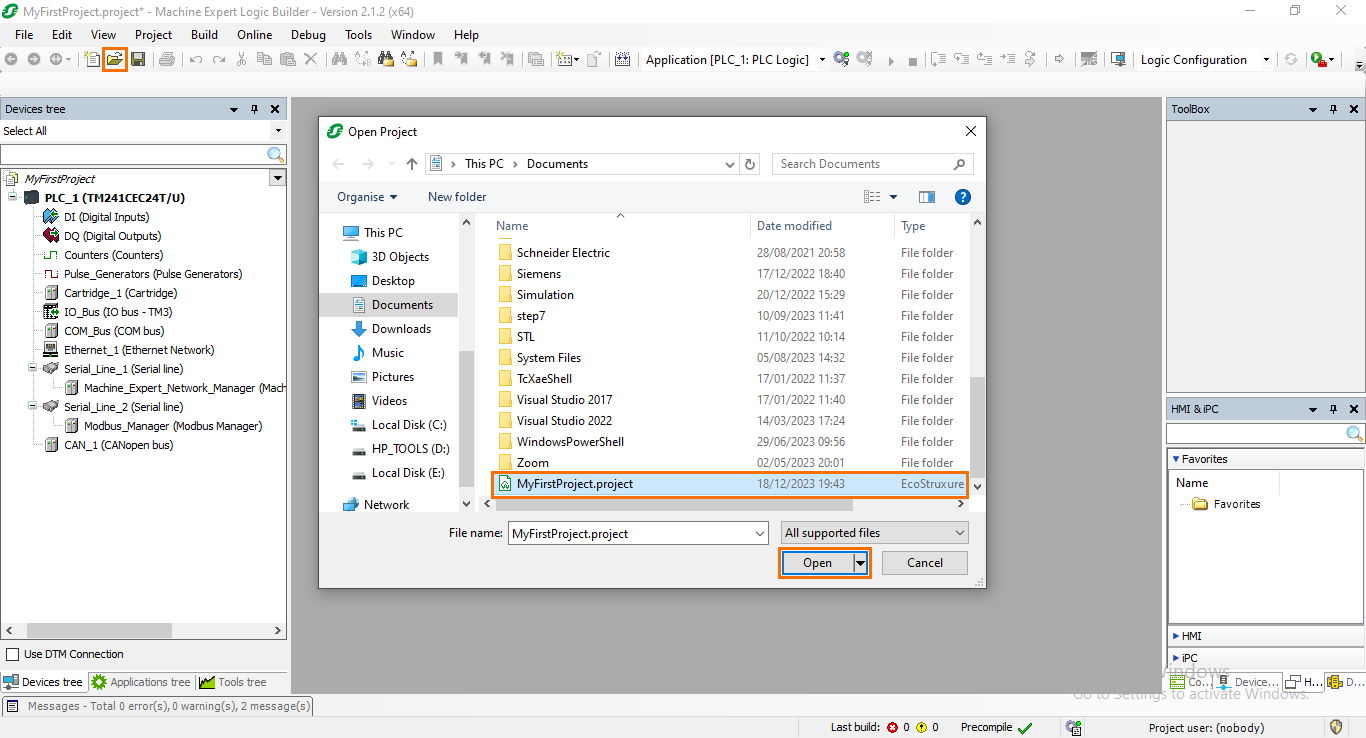
To open an existing project, click on the “Open” button. This can also be done by clicking on File -> Open. Then, select the project you want to open and click on “Open.”
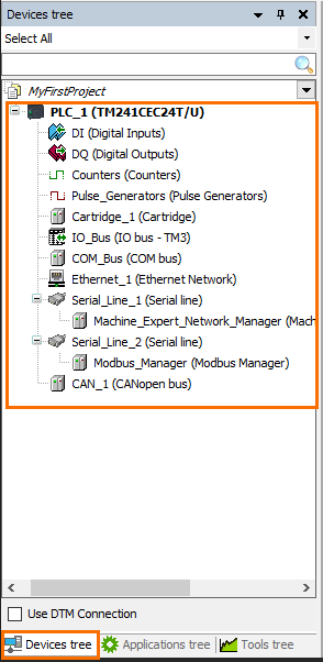
Machine Expert’s Device Tree
As mentioned earlier, all components and features of the Machine Expert project are divided into three project trees. You will have to navigate through these trees to configure and program your controller. The “Device Tree” contains all the hardware-related configurations of your project, such as I/O ports, extension modules, fieldbuses and communications…etc. Its content varies depending on the function of the controller type selected. For example, some controllers may have built-in physical I/Os or require extension modules; they can also have different types of fieldbuses ports…etc. The Device tree will always contain all the hardware features present in your controller model.
Digital inputs and outputs
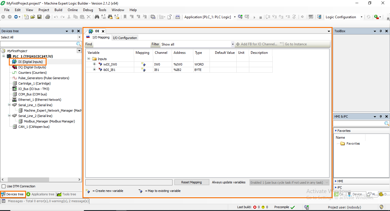
The TM241CEC24T/U controller we selected includes integrated digital inputs and outputs that can be accessed from the Device tree directly. Open the “DI (Digital Inputs)” section. Here, you will be able to configure the controller's built-in DIs.
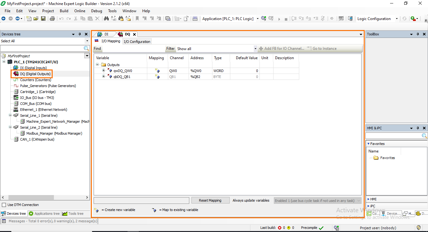
The same logic applies to the “DQ (Digital Outputs)” section. Here, you will be able to configure the controller's built-in DQs.
Please note that other sections may appear depending on the hardware features of your controller. For example, the TM241CEC24T/U model we selected also has built-in counters for frequency inputs and pulse generator outputs. Some other models may also have built-in analog inputs/outputs…etc
Extension modules - I/O Bus
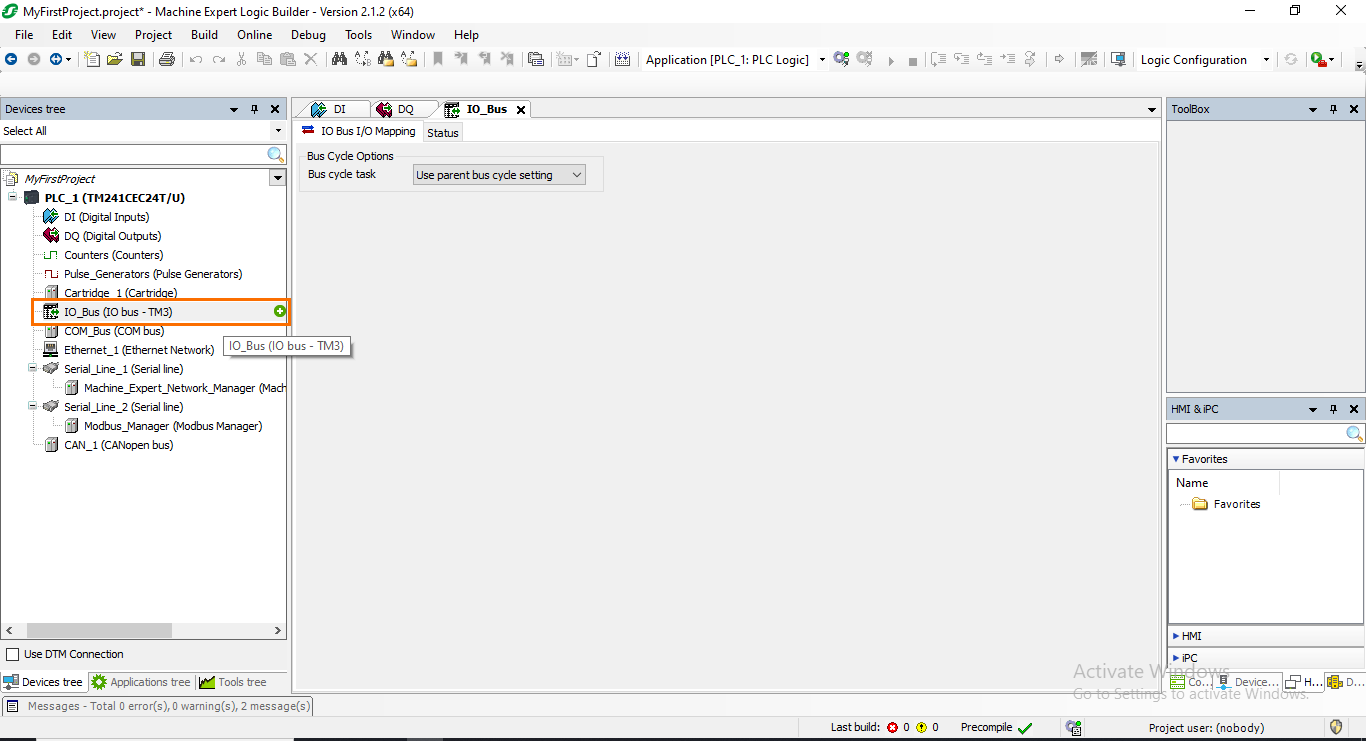
After covering the integrated I/Os, let’s head now to the extension modules. Like the vast majority of PLCs, it is possible to extend the number of inputs and outputs of your system by adding modules. This can be done in the “IO_Bus” section. Here, you will be able to add modules and configure them. To add a module, place your cursor at the top of the “IO_Bus” section. A green plus icon should appear on the right of the section. Click on it.
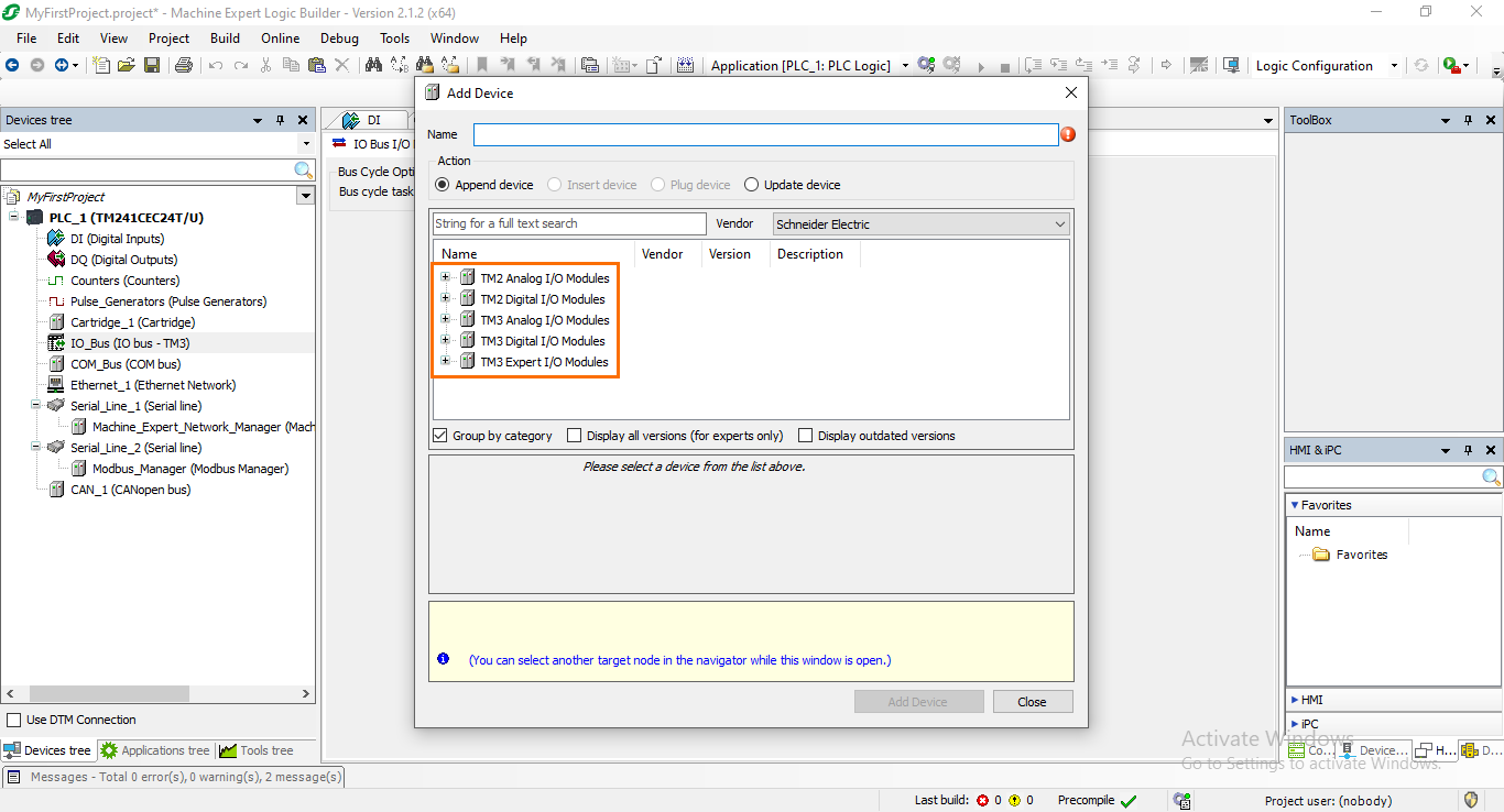
This will open a device catalog that includes all the modules available that you can add to your system.
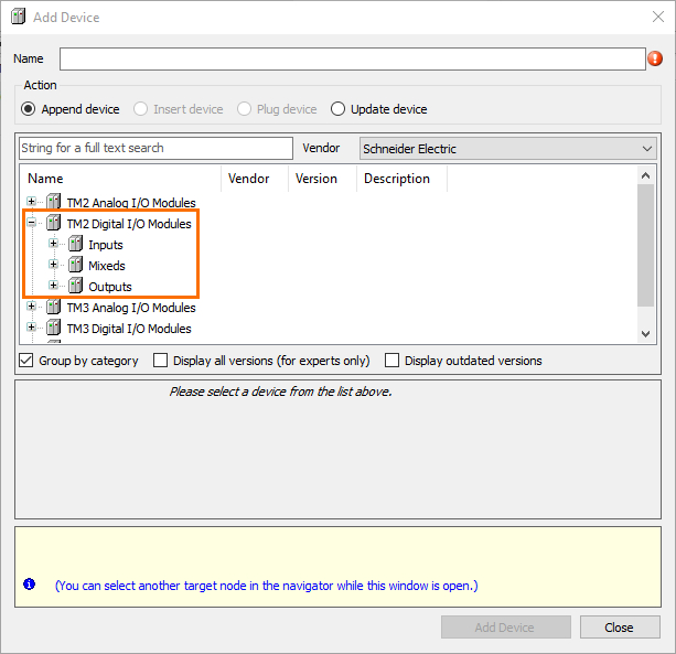
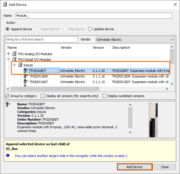
Let’s add a basic 8*DI module. First, open the “TM2 Digital I/O Modules” section. You will find three sections: Inputs, Outputs, and Mixed.
Then, pen the “Inputs” section and select the “TM2DAI8DT” module. Once done, click on “Add Device.”
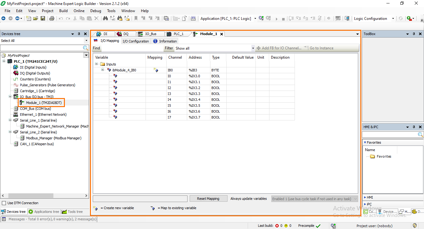
You should see the added module appear under the IO_bus section. If you open the module, you will find an interface similar to what we saw earlier with the integrated I/Os. You will be able to configure the module channels here.
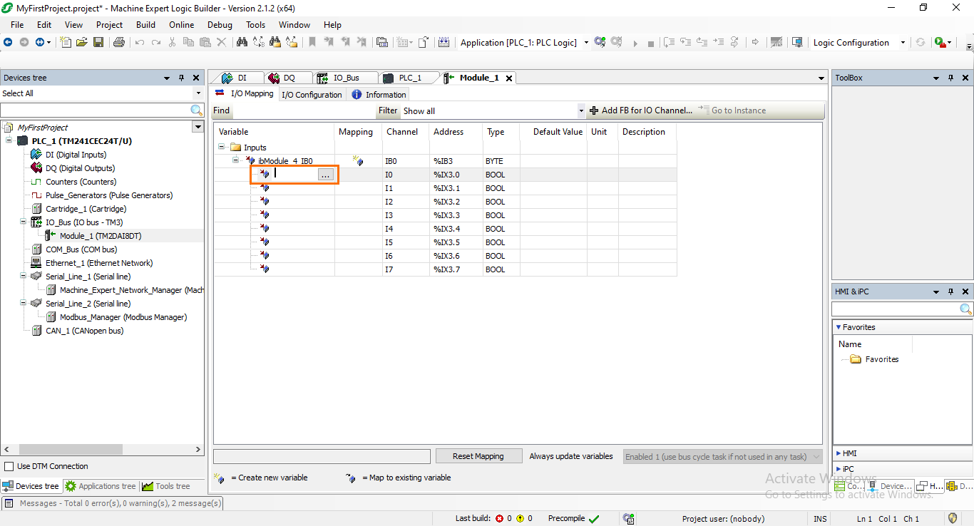
You can give every channel a variable name so that they can be used in your programs. To do it, click on the “Variable” section of the channel you want to name. It will become editable.
Then type the variable name you want to give it. For example, if this would be an input connected to a start button, you can name it “Start_button.”
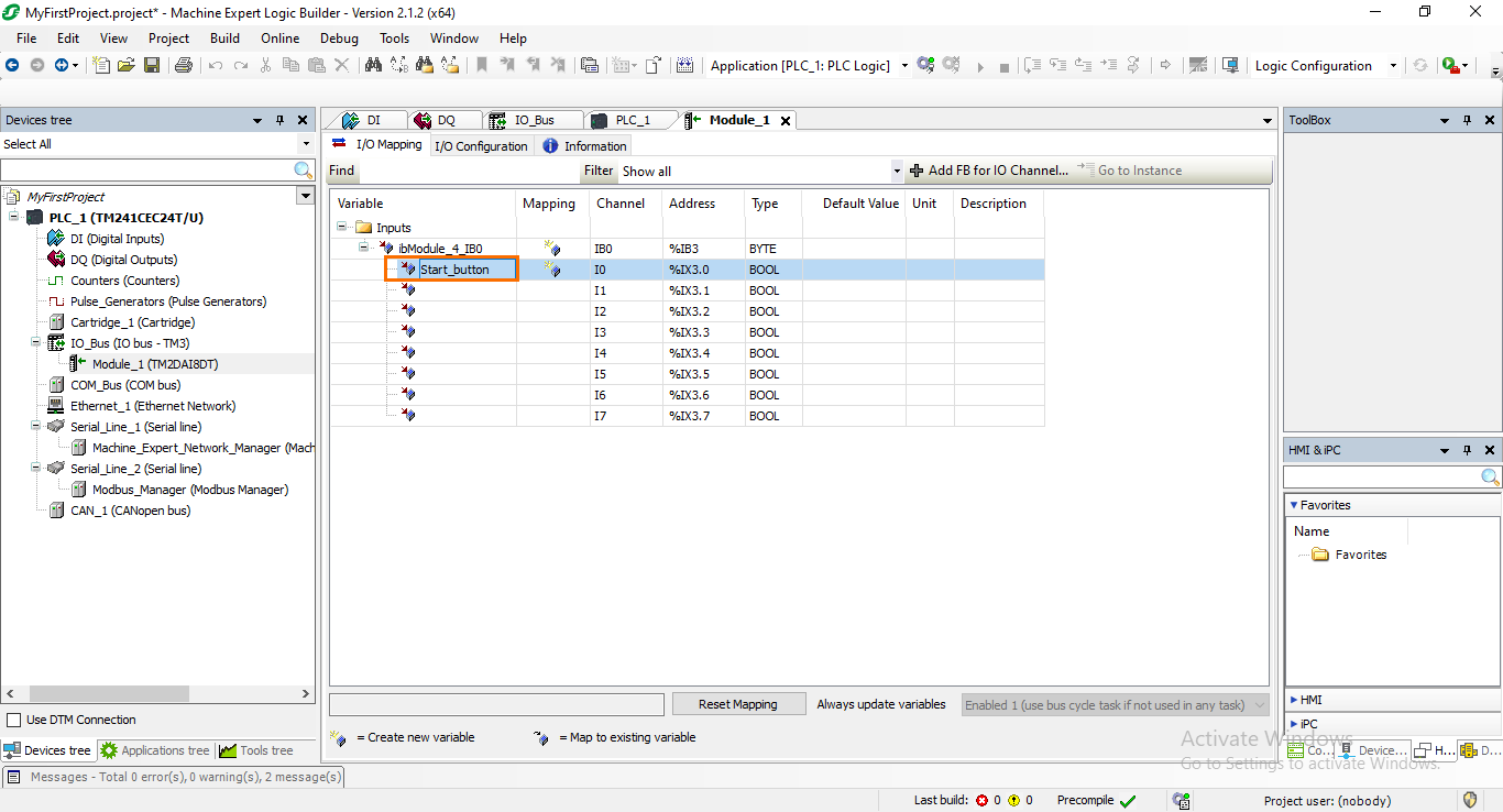
Please note that the integrated I/O channels can also be named using the same method.
Ethernet interface configuration
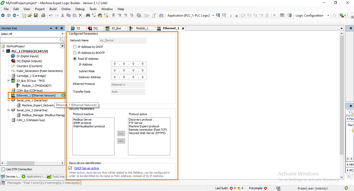
The next important section you will come across during your work on your project is communication. Each Schneider PLC model has communication interfaces such as Ethernet, Serial, CAN….etc. These interfaces will be displayed in your Device tree. Let’s try to configure the Ethernet interface of our TM241CEC24T/U controller. Click on the “Ethernet_1 (Ethernet Network)” section in the Device tree. Here, you will be able to configure the IP address and security parameters of the Ethernet interface.
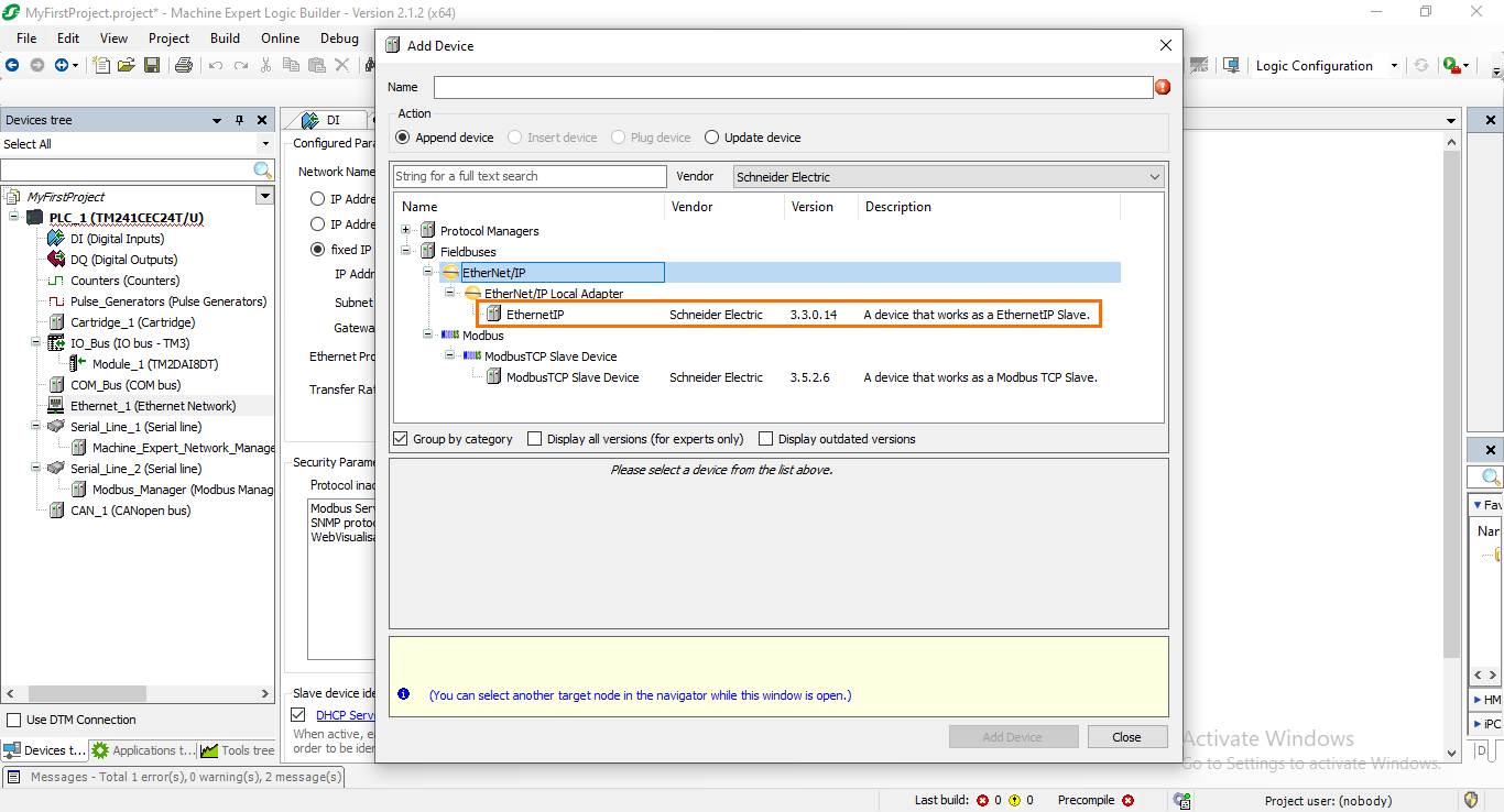
After configuring the interface, we must add a communication protocol that will be associated with this interface. Click on the green plus button next to the “Ethernet_1 (Ethernet Network)” section. This will open a small window where you will find all the Ethernet protocols available. If you open the “Fieldbuses” section, you will find two TCP/IP-based protocols: Ethernet/IP and Modbus TCP. Select the “EthernetIP” protocol.
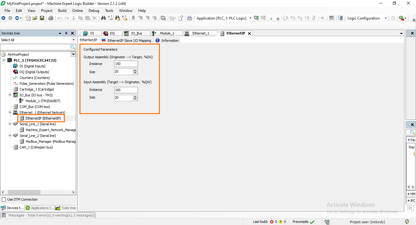
You should see the newly added protocol appear in the Device tree under the “Ethernet_1” section. By opening it, you will find further parameters about the memory addressing used in the protocol.
Machine Expert’s Application Tree
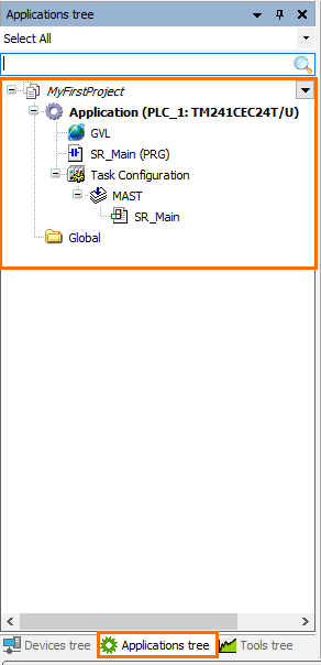
We have now covered the hardware section of a Machine Expert project, let’s head now to the software side. Everything that is related to PLC programming is located in the Application tree. To access it, click on the “Application tree” tab. Here, you will find all your PLC tasks, programs, and Global Variable Lists (GVL).
Global Variable List (GVL)
Let’s have a look first at the GVLs. As their name suggests, these are variable lists that can be accessed globally by any part of your program. They can be used as a way to define the variables you may need in your program or to organize variables as databases.
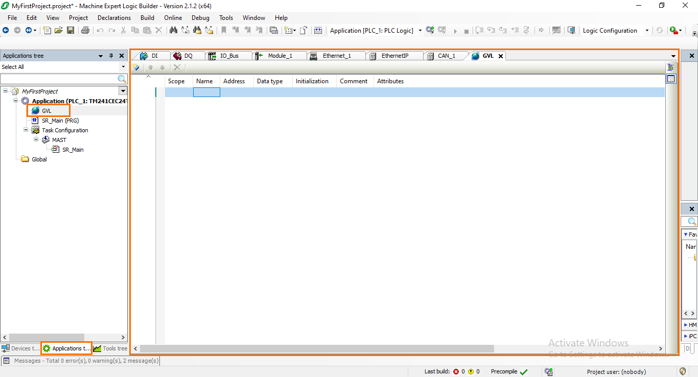
By default, a GVL is already created in your Application tree. If you open it, you will find the interface where you can define variables.
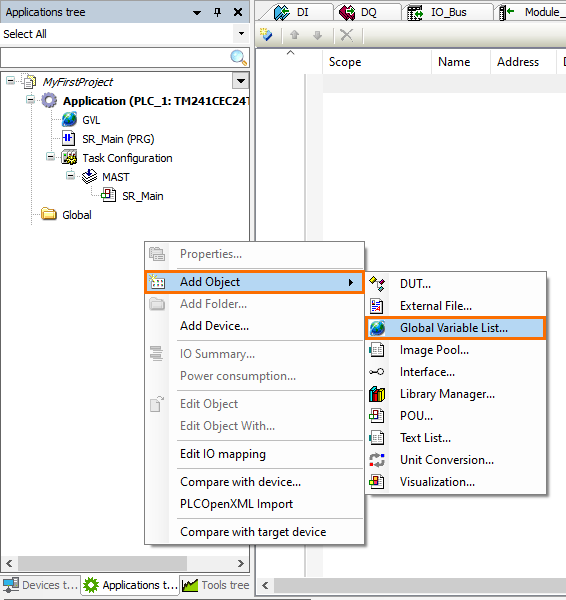
To create a new GVL, right-click on the blank space of the Application tree, then go to “Add Object” and select “Global Variable List.”
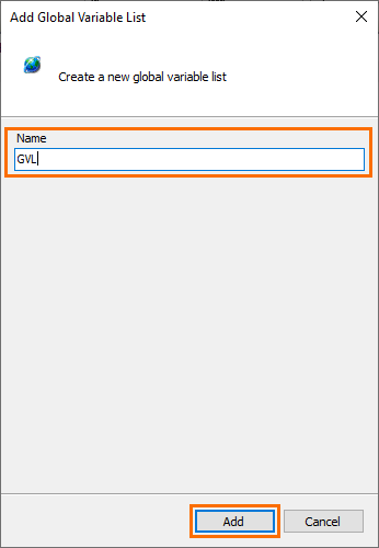
This will open a small window where you can edit the name of the new GVL. Once done, click on “Add.”
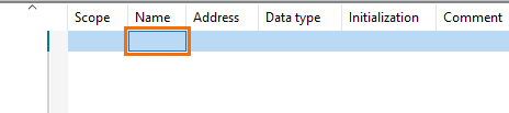
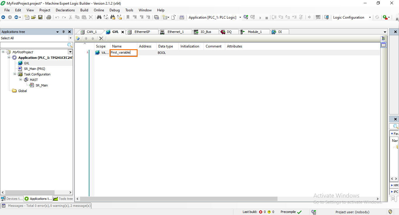
To create a new variable in your GVL, click on the name section of the first row to edit it.
After that, type a name of your choice for the variable. Then, press Enter. When the variable is created, you should notice that a default data type (BOOL) has been assigned to the variable.
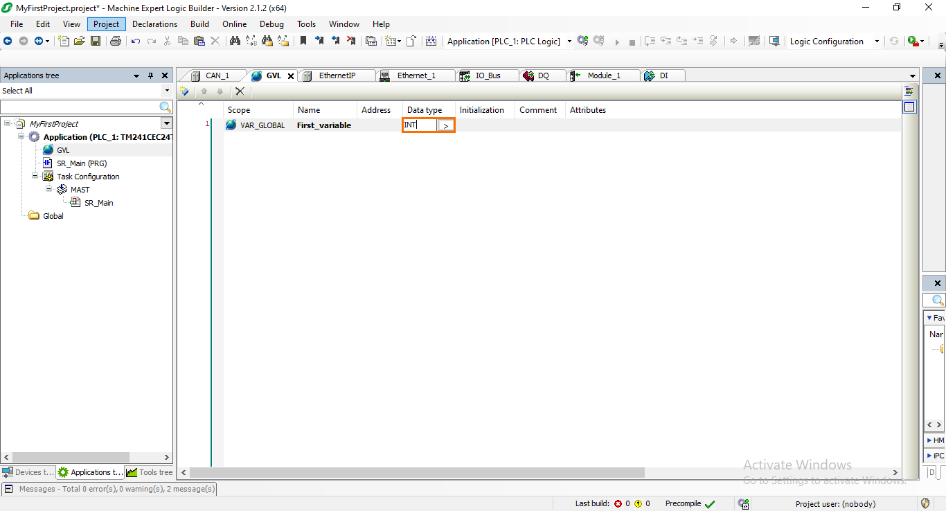
You can edit the Data type of the variable by typing the desired type. For example, to make it an integer, type “INT” in the Data type section of the variable.
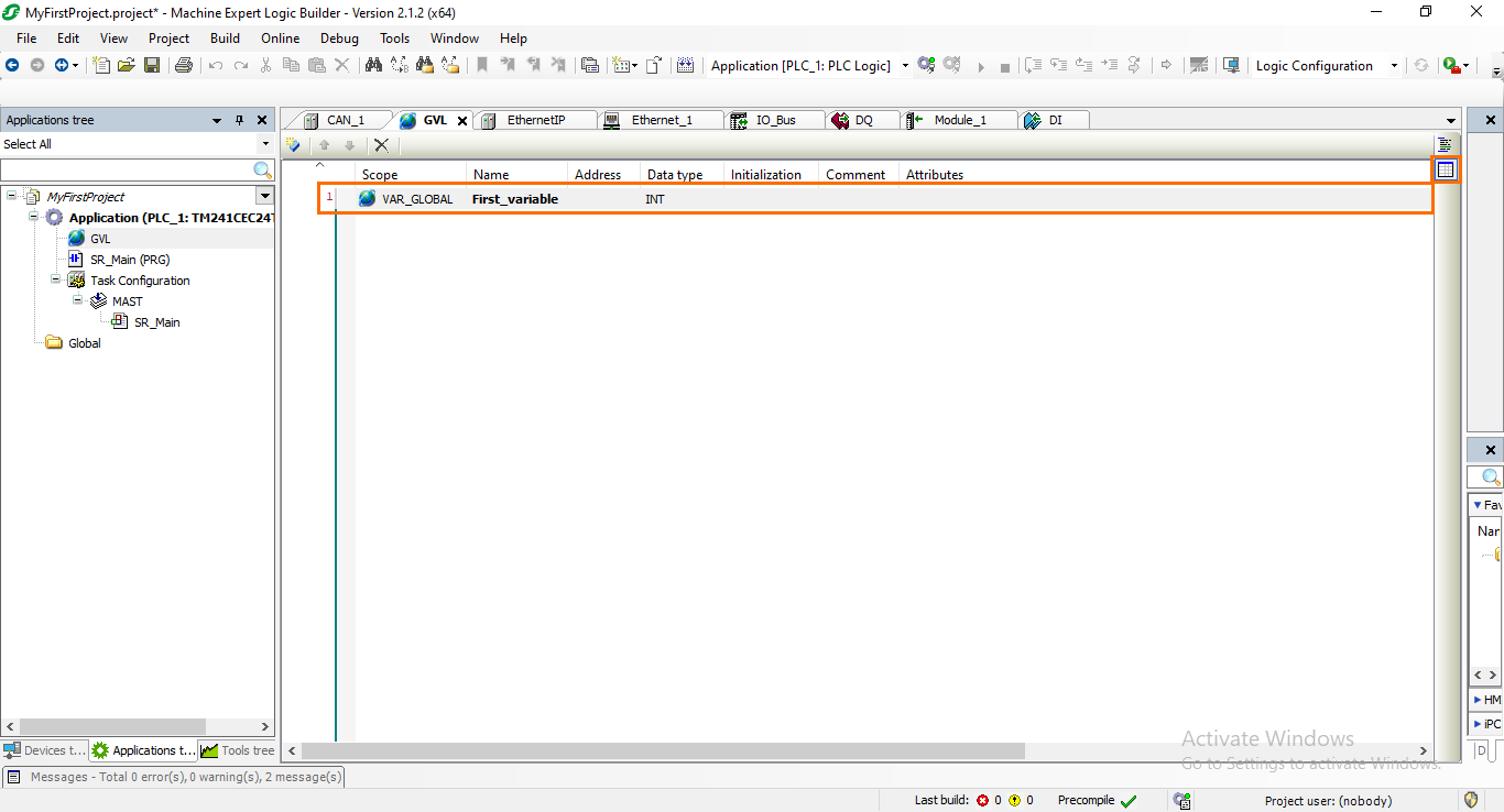
Once done, the variable has been created. For now, we are using the tabular view of the GVL that displays the variables in a table where you can edit further details about the variable such as the address, initialization, comment…etc. The tabular view is indicated by the table icon on the left side of the interface.
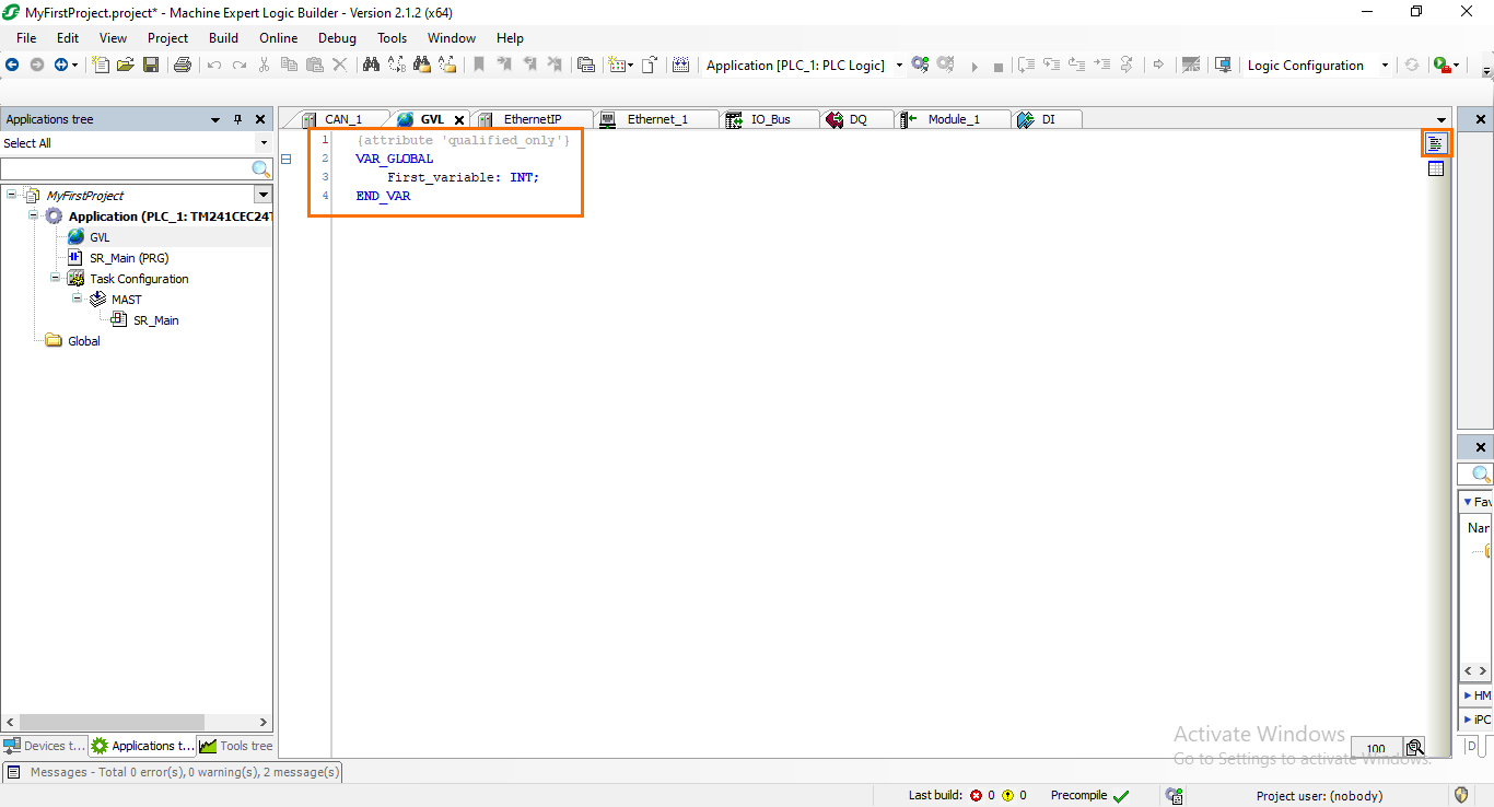
However, it is also possible to display the variables in a textual format that will allow you to define variables using a Structured Text interface. To access the textual view, click on the “Textual view” icon above the tabular view icon. Here, you will be able to define variables textually as you would do in an ST program.
PLC tasks
We have covered the variables’ side, so let’s head to the program side now. If you are not familiar with how PLCs execute programs, they are executed in a cyclic manner and organized into tasks. Each task consists of a set of programs, functions, and function blocks (Also known as POUs, Program Organization Units) that are processed sequentially, with the PLC repeatedly cycling through these tasks to control and monitor various processes in real-time. For any POU you want to execute, it will need to be called somewhere within a task.
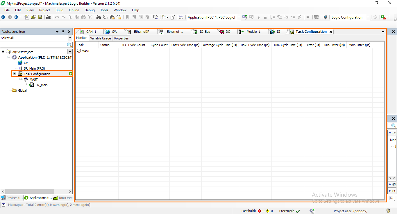
Let’s have a look at how tasks work in Machine Expert. In your Application tree, open the “Task configuration.” Here, you will be able to manage and configure your PLC tasks. By default, a task called “MAST” (Master Task) is created and can serve as your main task to execute programs.
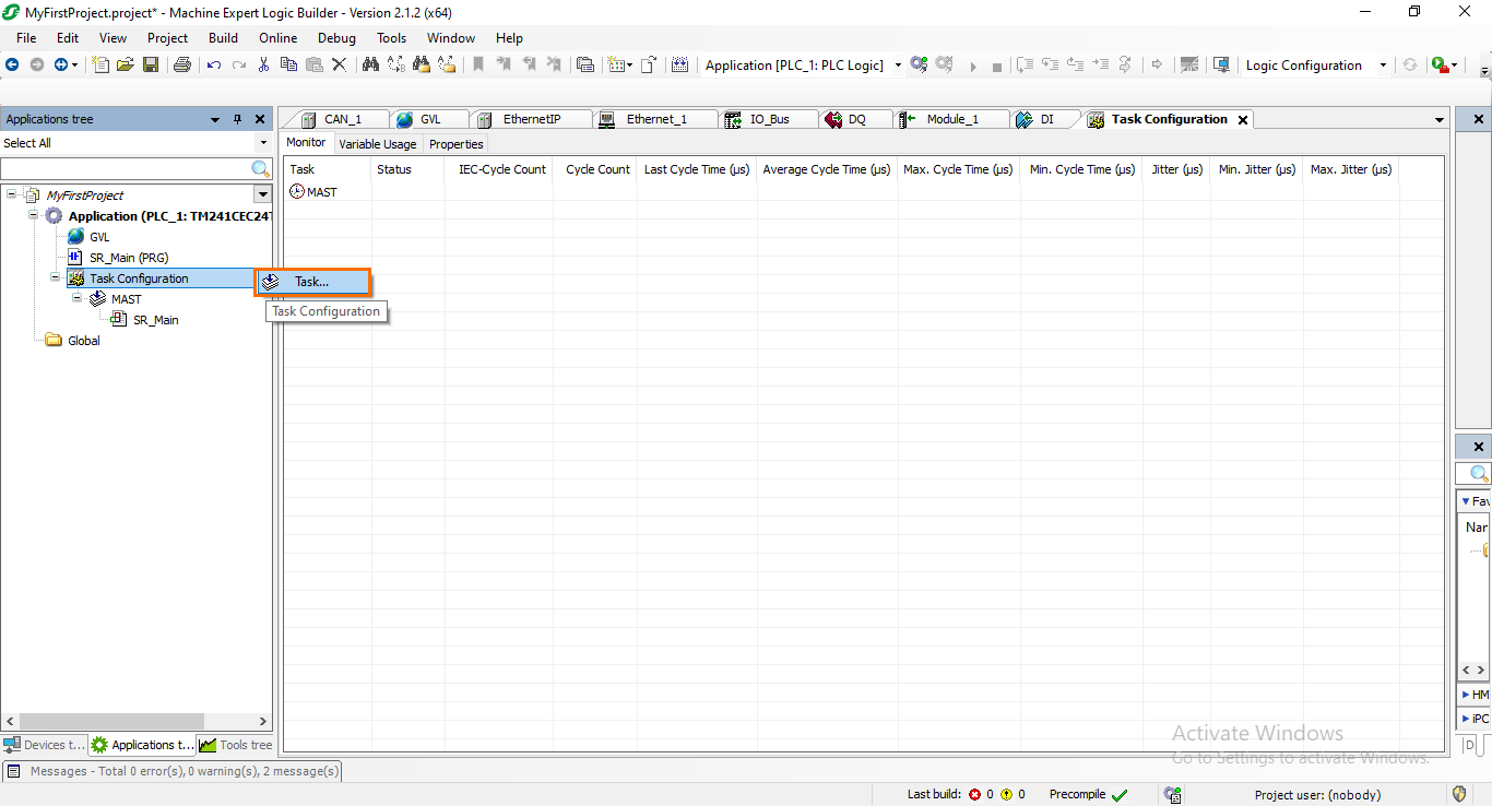
You can create new tasks by clicking on the green plus icon next to the “Task configuration” and then selecting “Task.”
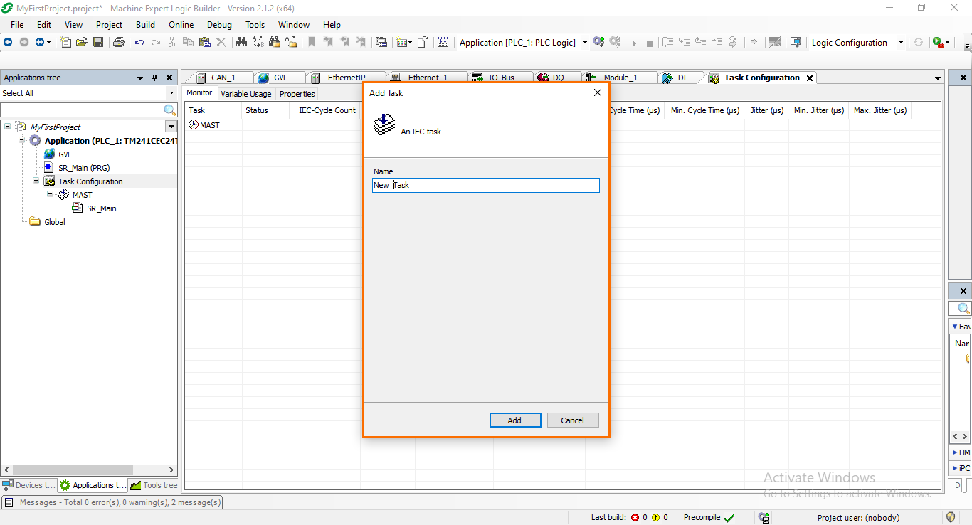
After that, a small window where you can define the name of the task you want to create. Once done, click on “Add”.
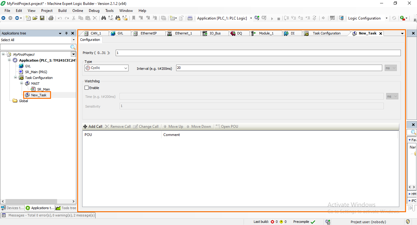
The newly created task should appear in your Application tree under the Task configuration section. If you click on it, it will open the task’s properties where you can define the task type, priority, and POU calls.
There are four types of tasks in Machine Expert:
- Cyclic: The task will be executed cyclicly according to the set time interval.
- Event: The task is triggered by a rising edge on a defined variable.
- External: The task is triggered by an external event, such as errors, alarms, and system processes.
- Freewheeling: The task will be executed cyclicly but not according to a set time. Instead, as soon as a cycle ends, the next one will start immediately.
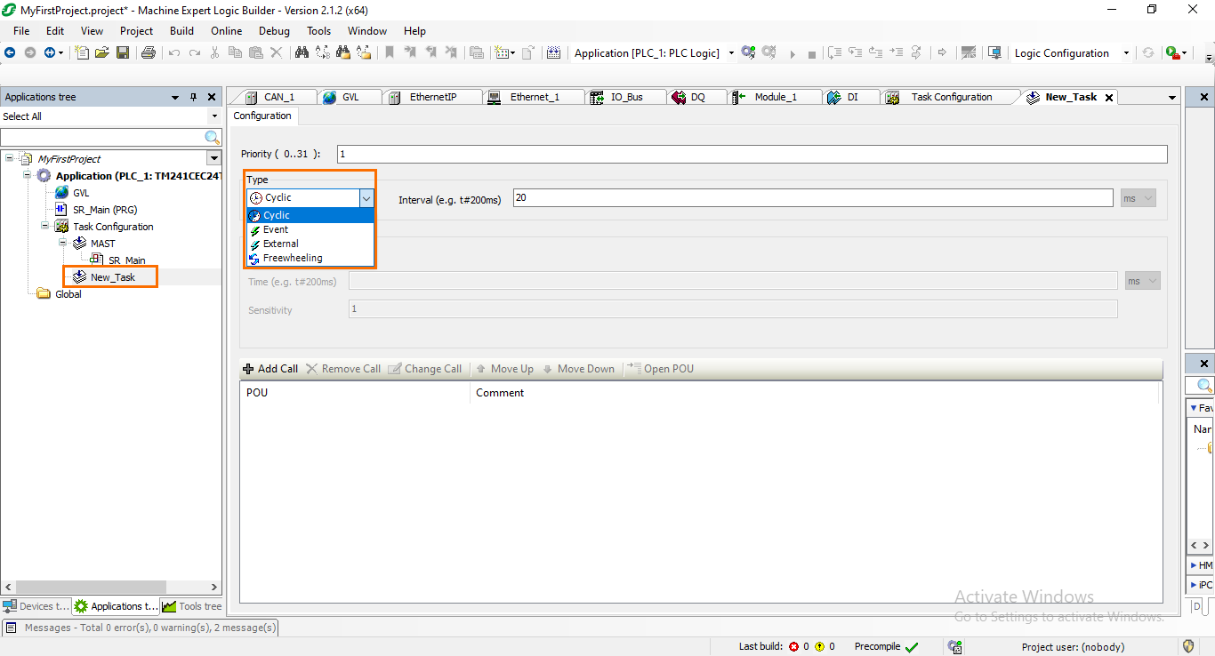
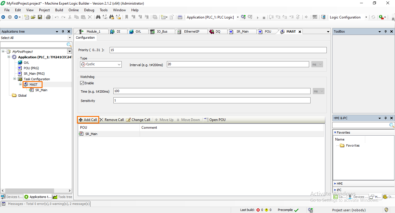
Let’s shift our focus back to the default MAST task. If you open it, you will notice that it is set as a cyclic task with an interval of 20 ms. It is also called the “SR_Main,” which is a program created by default.
Program Organization Unit (POU)
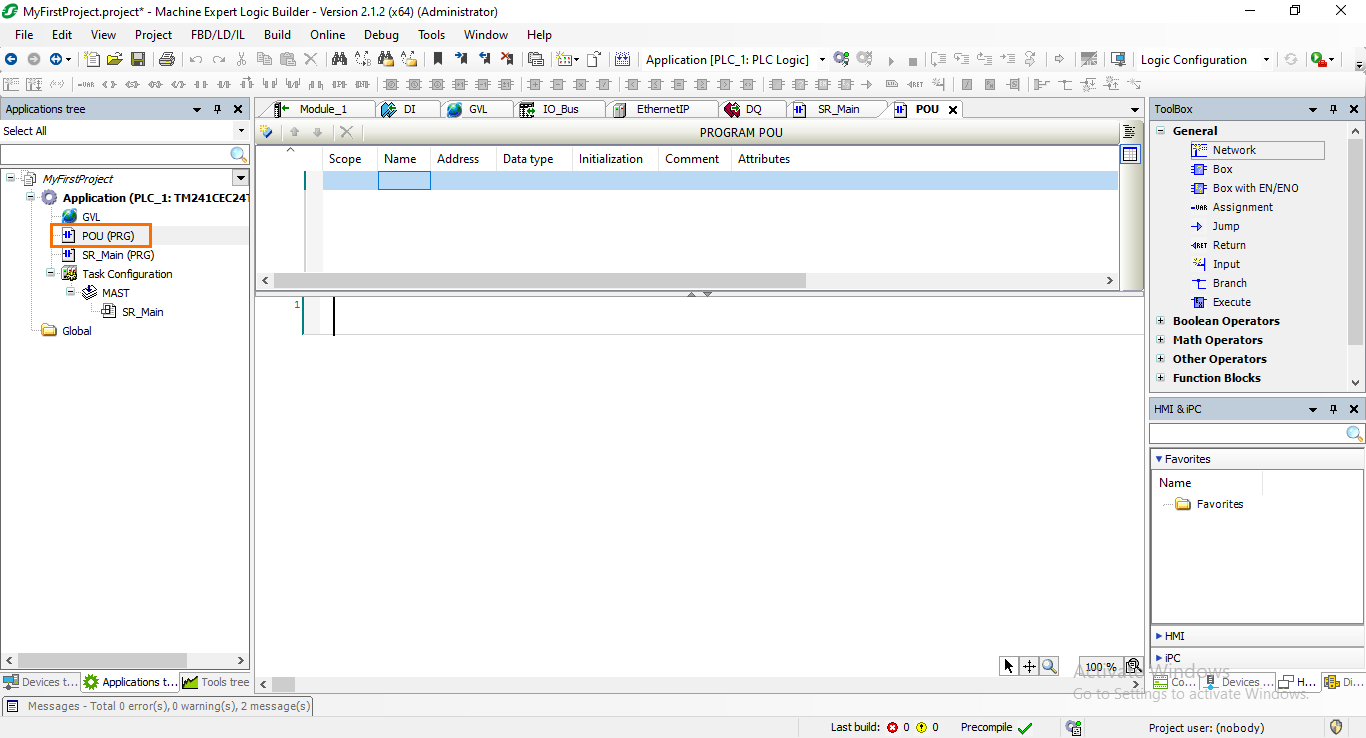
We come now to the last aspect of this section of the tutorial, the Program Organization Units. As we just mentioned, a program created by default named “SR_Main” is called in the MAST task. This program is intended to be the main program of your PLC application. Let’s open it and have a look at Machine Expert’s programming interface.
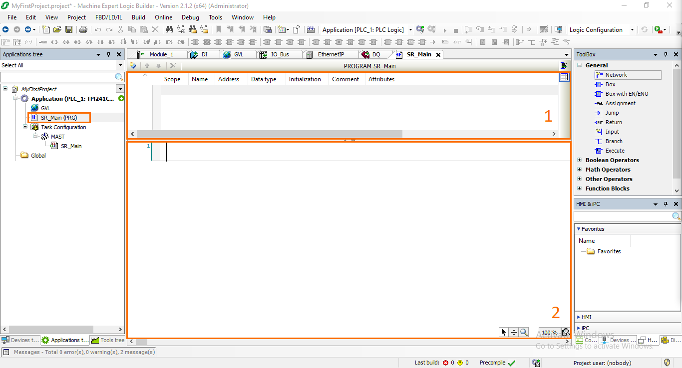
The programming interface is split into two sections:
- Declaring zone: This is where you declare all the local variables and instances of the POU.
- Programming zone: Where the actual programming is done by assembling sequences of instructions.
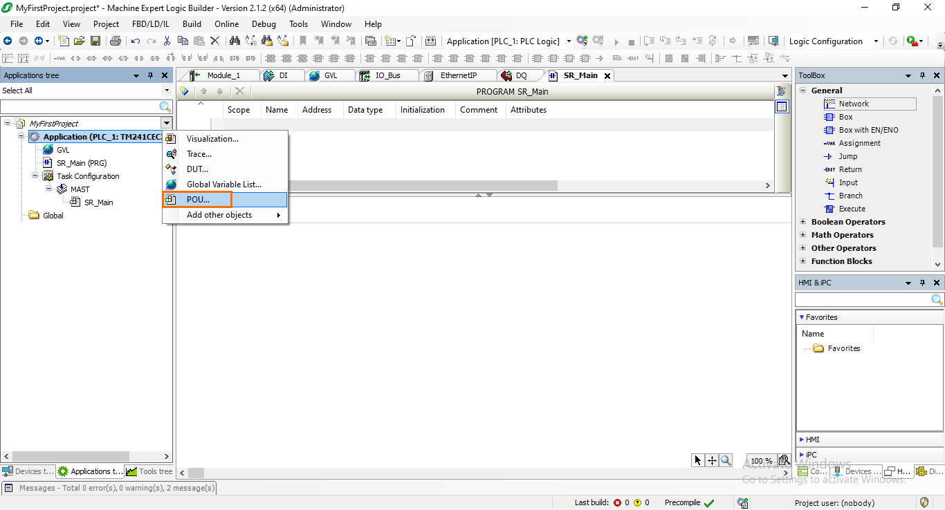
To add a new POU, click on the green plus icon next to the “Application” section and select “POU.”
A small window will open where you can define the POU’s name, type, and default language.
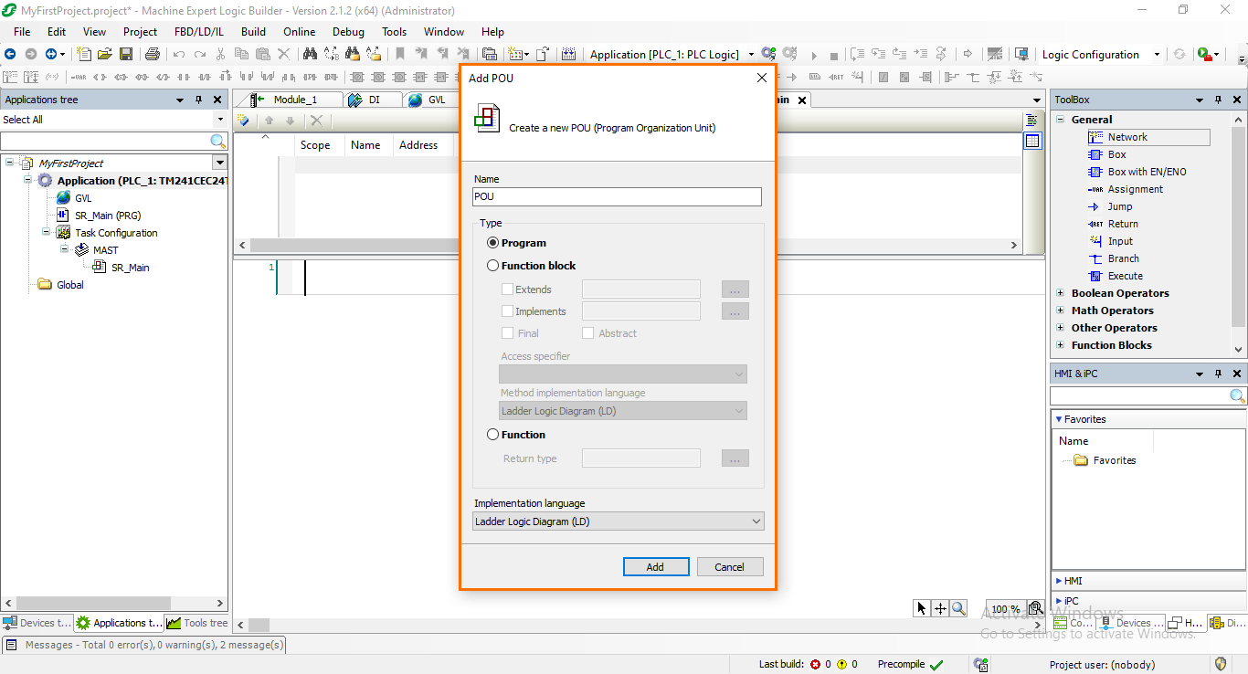
There are three types of POUs:
- Program: Programs are software units that are usually used to call other functions or function blocks, but they can also contain instruction sequences. Programs have an internal memory, cannot be called by other programs but by tasks, and do not have Inputs and Outputs.
- Function Block: FBs are software units with multiple input/output parameters and internal memory. The value a function block returns depends on the value of its internal memory. Within a function block, it is possible to call other function blocks or functions, but not programs and recursive calls are not allowed.
- Function: Functions are software units with multiple input parameters and exactly one output parameter (return value). As functions do not have an internal memory, calling a function with the same values always returns the same result.
Once you are done configuring the POU, click on “Add.” You should see the POU appear in the Application tree.
Now that we created a new POU unless we call it in a task, it won’t be executed. To call a POU in a task, go to the selected task (MAST) and click on “Add Call.”
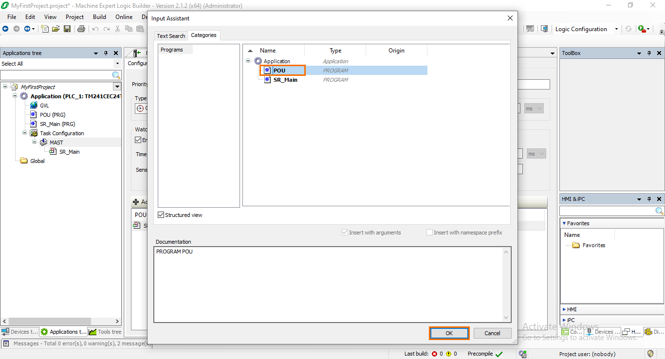
A window containing all the available POUs to call. Select the newly created POU, then click on “OK.”
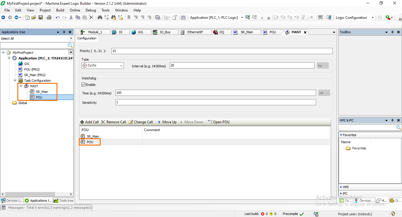
You should see the POU appear in the calls list of the MAST task.
Conclusion
In this tutorial, you learned how to navigate Schneider Electric's Machine Expert, starting with the foundational steps of creating a new project. Beginning with the software's interface overview, you gained familiarity with the essential sections such as the Project trees and Workspaces. The tutorial guided you through the configuration of hardware settings in the Device Tree, covering aspects like digital inputs and outputs, extension modules, and communication interfaces. You also explored the software side with the Application Tree, delving into Global Variable Lists (GVL), PLC tasks, and Program Organization Units (POUs).
Now that we've gained a general view of Machine Expert, the upcoming tutorials will delve into the practical application of the software for PLC and HMI programming. These future guides will provide hands-on insights into utilizing Machine Expert's capabilities to program PLCs efficiently and create intuitive HMI designs.
