PLC Sequencer Programming - Tutorial on SQI SQO Instructions in RSLogix 5000 Ladder Logic

Introduction
Programming a Sequencer in Ladder Logic on a PLC is an advanced skill. It’s a technique which utilizes SQI and SQO instructions in order to create a sequence of events which is based on specific steps & allows the PLC to follow a prescribed sequence of events. Although the squencer isn’t something you’d expect to use on a regular basis, it’s an advanced technique which shines in specific applications.
In this tutorial, we will be going over the use cases of a sequencer, how the SQI and SQO instructions are setup as well as a practical example of a sequencer.
The Sequencer Implementation Strategy
At the core, the sequencer is built from three components: Inputs, Outputs & Step Logic. The inputs are used to determine what’s currently energized and how it enables the sequencer. The outputs are used to identify what needs to be enabled at each step of the sequence. Lastly, the step logic is what will control what’s required to transition from one step to another and which outputs need to be set in a specific step.
A sequencer will work best in applications which are defined by multiple steps which are dependant on each other. As you develop PLC based applications, you will develop an intuition on where to use sequencers. A general rule of thumb is that if you have a process with 3 steps or less, you may implement a simple routine which goes through a series of MOV Instructions instead of a sequencer. As you go beyond this limit, the sequencer will be the preferred method of choice.
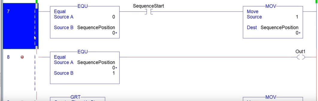
PLC Programmers have gotten used to implementing a sequencer through the use of MOV Instructions as mentioned above. Although this technique isn’t advised for larger applications; here’s an example of how this works:
- An integer is created & will be used to store the current step of the sequence.
- A MOV Instruction is used to change the step of the sequence by writing a specific value into the integer created above.
- An EQU Instruction is used to compare the value to a constant & allow certain actions to be carried out accordingly.
- Once the actions have been completed, the next step is initiated.
- The process is repeated until there aren’t any steps or the sequence is reset.
Sequencer Implementation through SQI & SQO Instructions
The example above illustrates the way the sequencer should work, but not the proper implementation. The flaws of the MOV Instruction as a sequencer become apparent as the application grows, changes need to be made and the application is passed down to a different party. It works in theory but isn’t designed to scale.
The solution is to use the pre-defined RSLogix / Studio 500 & 5000 Instructions SQI and SQO; sequencer input and sequencer output respectively. These instructions standardize & simplify the creation of the logic discussed above. They give the programmer a simple way to define the number of steps the sequencer needs to go through, which inputs & outputs need to be energized and provide a clear path to modifying current steps in order to accommodate new code or scaling.
Although this may seem like the perfect solution, it takes a little bit of practice in order to understand the functionality of SQI and SQO instructions. As mentioned above, the SQI is responsible for checking the inputs. Through a series of matrices, the instruction will monitor the inputs at every step. Similarly, the SQO will be responsible for setting certain outputs based on the step the sequencer is in.
Working with an SQI Instruction
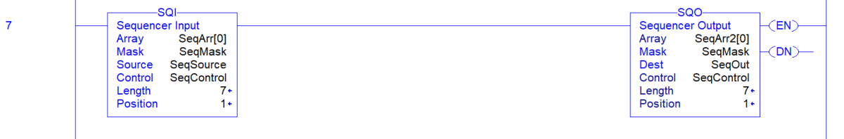
The SQI has several elements: SeqArr[0], SeqMask, SeqSource & SeqControl. Let’s examine them in detail.
SeqArr is an array. Each element of this array will define which inputs need to be energized in order to transition into the next step of the sequence. For example, if the first array specifies elements 3 and 4 to be energized, this translates into bits 3 and 4 of the first element of this array to be set.
The SeqMask is a binary mask which will determine which bits need to be examined by the instruction. The functionality of this element is exactly the same as in the Masked Equal Instruction.
The SeqSource is the current state of the instruction and will transfer the array element from SeqArr[x] where x is equal to the current step of the sequence.
The SeqControl is a CONTROL based instruction which takes care of the backend functions of the instructions.
Lastly, two constants are displayed in the instruction: Length and Position. The length constant may be changed by the user and will define the number of steps the sequencer will go through before the end. The position is an internal variable which will display the current step
Writing Outputs through the SQO Instruction
The SQO instruction will accomplish the complementary action of the SQI. As the step transitions to a new one, the SQO will pull from the array in order to energize the outputs specified by the bits.
Deploying a Sequencer for a Tank Filling Application
At this point, you should have a general idea about the functionality of the sequencer & SQI / SQO instructions. The best way to learn their usage is through a simple real-life example.
The process begins as the operator pushes the Start Button on an HMI. Once the button is pressed, the system begins a batch. The first requirement is to fill the tank to 30% with water. Once we reach the said level, we need to add a 2nd liquid ingredient until the tank level reaches 70%. Finally, we need to add a solid ingredient until the tank is full. As we begin adding a second ingredient, we need to start mixing until the end of the process. Once we’ve filled the tank, we need to start heating the mixture. Once the mixture reaches 220degF, we need to keep heating for 30 seconds. At the end of this process, the batch is ready for the operator to transfer.
The above requirements should translate in your mind into something which resembles the following:
- Step 1 – System is waiting for Start Button input | Output energized: System Ready for Batch
- Step 2 – System is waiting for the Level to Reach 30% | Output energized: Water Input Valve
- Step 3 – System is waiting for the Level to Reach 70% | Output energized: Liquid 2 Input Valve & Stirrer ON
- Step 4 – System is waiting for the Level to Reach 100% | Output energized: Solid Ingredient & Stirrer ON
- Step 5 – System is waiting for the Temperature to Reach 220degF | Output energized: Heating System & Stirrer ON
- …
In other words, you will need to translate the “English based” requirements into PLC logic which can be applied to the system at hand. As you program the logic into the SQI and SQO instructions, you must go through this sequence multiple times in order to test it prior to deployment. Don’t hesitate to enable the instruction and manually step through the inputs while checking outputs.
Conclusion
Building a sequencer can be a challenging feat, but is extremely useful in certain applications. Having the knowledge & ability to design such applications can make your application robust, scalable & easy to understand. If done properly, you & other programmers will be able to review the arrays you’ve created and make changes or troubleshoot the application when necessary.
The sequencer leverages two key instructions: SQI and SQO. By setting the arrays within each one, you may step through a sequence by energizing specific inputs; the instruction will set the outputs based on the step you’re in.