Commissioning a Servo Motor with Siemens Sinamics Starter

Introduction
Sinamics Starter is the leading software from SIEMENS Automation for driver and servo driver configuration, parametrization, and control development. The proper commissioning of drivers is vital in ensuring secure and error-free operation of process control and machine operations.
This tutorial will discuss driver and servo driver commissioning utilizing the Siemens Sinamics Starter software.
Pre-Requisites
To follow along with this tutorial, you will need:
- A basic understanding of industrial networks;
- A basic understanding of motors and servo motors;
- Sinamics Starter v5.4 software.
Creating a new project and importing a drive in Sinamics Starter
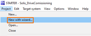
Create a new Starter project in Project > New with wizard.
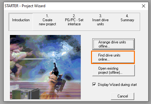
We will find an existing unit online and import its existing hardware configuration. It’s also possible to arrange offline hardware components for later commissioning.
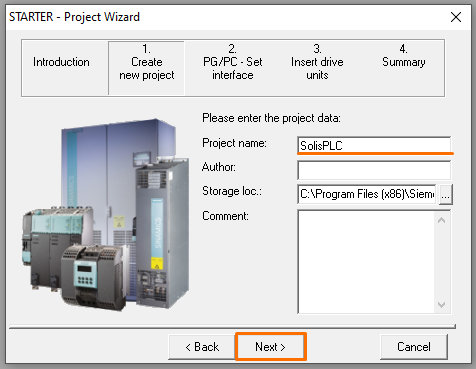
Setup a project name and project path and click next.
Next, set up the correct communication interface and communication driver. Open the PG/PC interface configurator and define the proper access path if needed. In this scenario, we’re communicating with the S110 Control Unit over Profinet, so the computer’s network adapter is the appropriate driver.
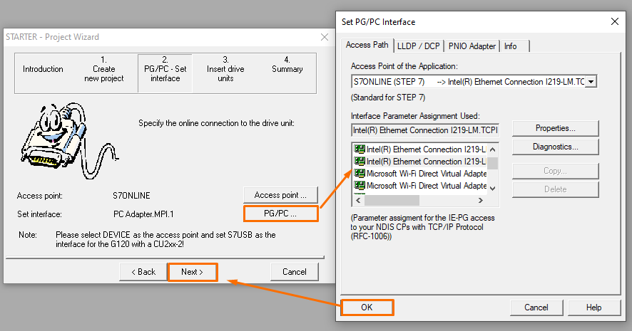
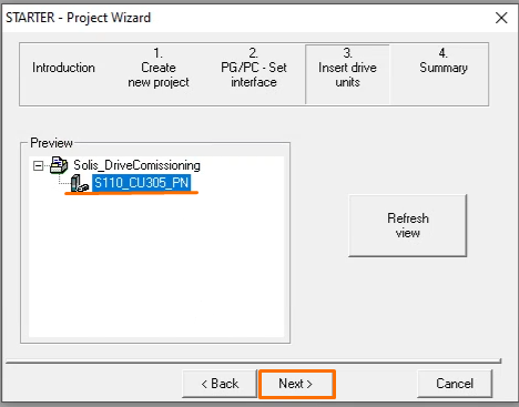
Once every communication configuration is done, the device should be accessible from the project wizard. Select the driver to import the existing hardware configuration into your project.
Configuring the drive unit in Sinamics Starter
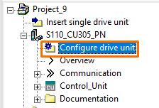
Now that the Control Unit has been imported to the project, it’s necessary to configure a drive unit to be controlled by the specified Control Unit. Each control unit is able to accommodate up to three power modules, and some power modules are able to power two different motors (double motor modules), which means a total of six possible motors attached to a single Control Unit. Double Click on Configure drive unit.
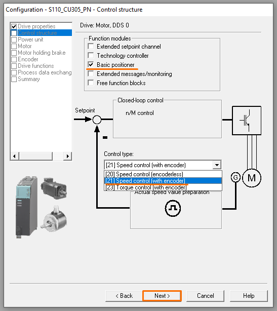
The drive control structure defines the main control variable(Speed or Torque control) and its general functional block diagram. Therefore, it’s essential to understand the needs of each application before deciding on the control mode.
Generally speaking, encoder control means a more precise control for positioning or precise speed and torque applications. Besides the control mode, Sinamics Starter offers function modules, which are configurable sets of predefined and customizable complex control functions, each recommended for some common applications. In this tutorial, we will utilize the Basic Positioner function module to commission simple, precise positioning tasks.
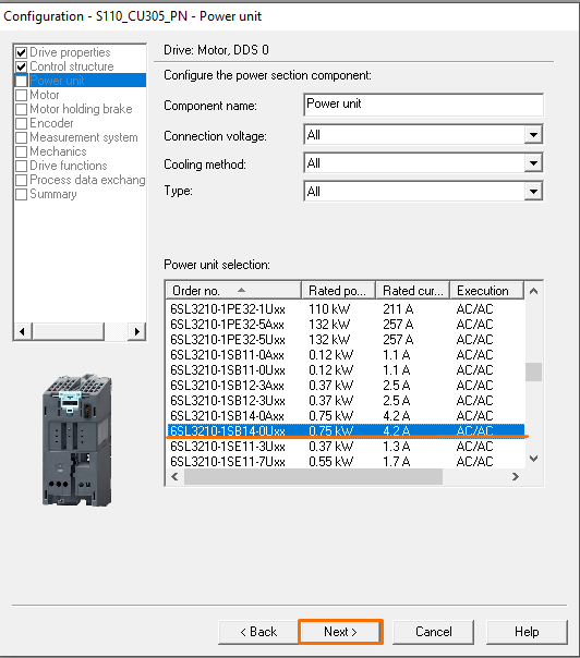
Select the correct power unit. Be aware of the specific filters for connection voltage, cooling method, and unit type.
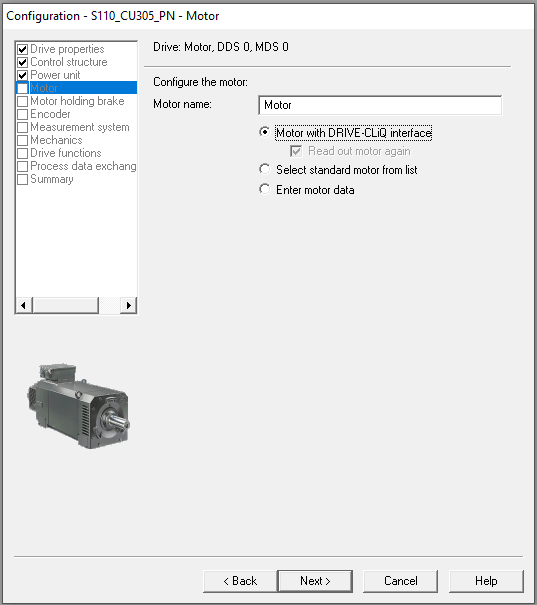
Most problems when commissioning servo drivers and inverters emerge from incorrect motor data input. Therefore, it’s crucial to ensure every motor specification matches the real motor specifications. This time, we’re configuring a motor with a DRIVE-CLiQ interface, an intelligent motor/drive interface capable of identifying all necessary motor(and even modules) configurations and minimizing development errors and inconveniences.
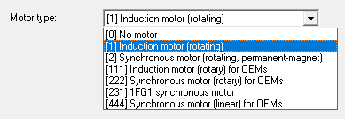
Besides the DRIVE-CLiQ interface, Starter accepts the configuration of most kinds of motors. It’s widespread to face general Induction motors in the industry.
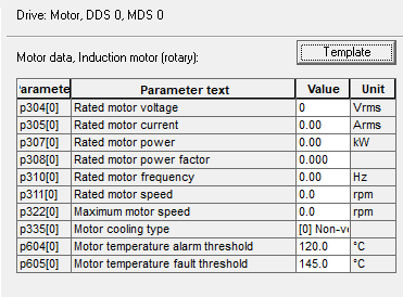
The main parameters to be defined for induction motors are:
- Motor Rated Voltage;
- Motor Rated Current;
- Motor Rated Power;
- Motor Rated Power Factor;
- Motor Rated Frequency;
- Motor Rated Speed;
- Maximum Motor Speed;
- Motor Cooling type;
- Motor Temperature thresholds.
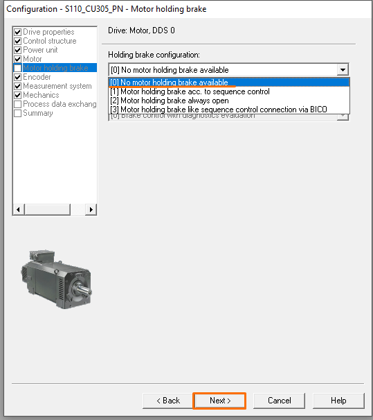
The next step is to configure the motor holding brake, if it exists.
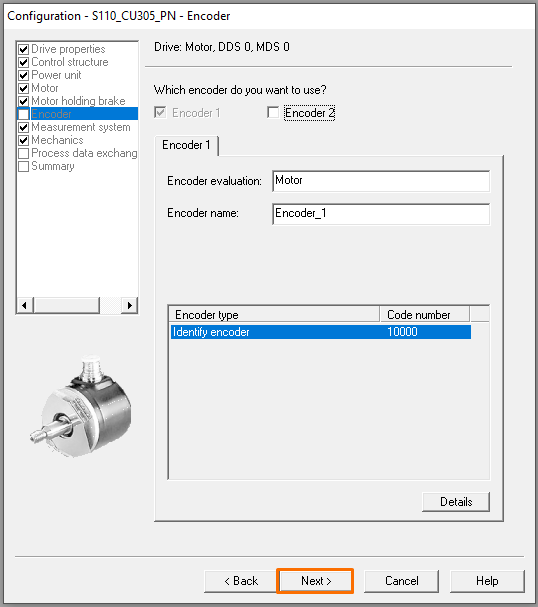
Since we’ve selected an encoder-based control mode, it’s necessary to configure the encoder to be used. A servo motor comes with an encoder attached to its structure, but it’s also possible to configure a second encoder if desired (or a primary encoder in case of common induction motors are being used).
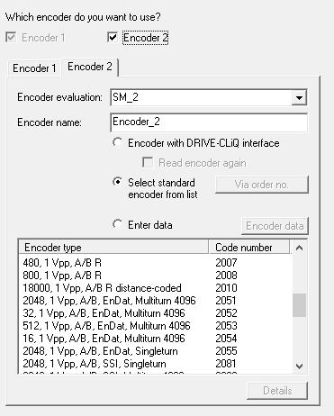
Additional encoder configuration should be addressed, whether it comes from the DRIVE-CLiQ interface, standard encoder list, or manual entry of data.
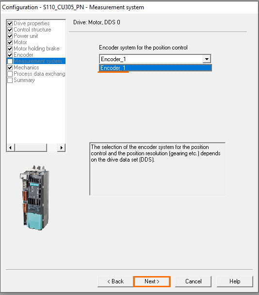
Select the desired encoder to be addressed in the positioning control functional diagram.
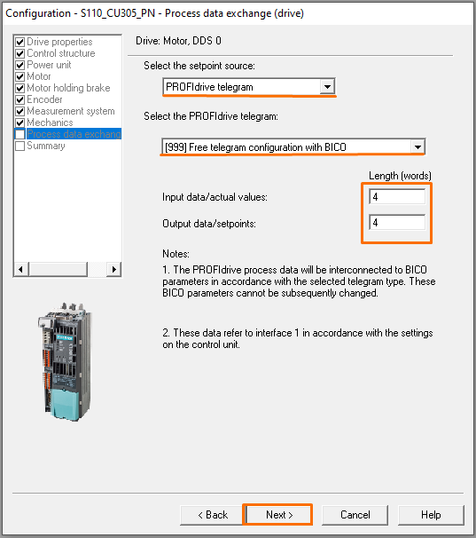
The setpoint source for our control shouldn’t bother us at the moment since we’re covering only fundamental commissioning via Sinamics Starter. Most applications, however, define a PROFIdrive telegram(data exchange with the PLC from the PROFINET interface) to read setpoints from the PLC. A Free telegram means the developer chooses any number of Read and Write words to be exchanged with the PLC. A basic positioning application is practicable with a 4/4 free telegram.
Going online with the device
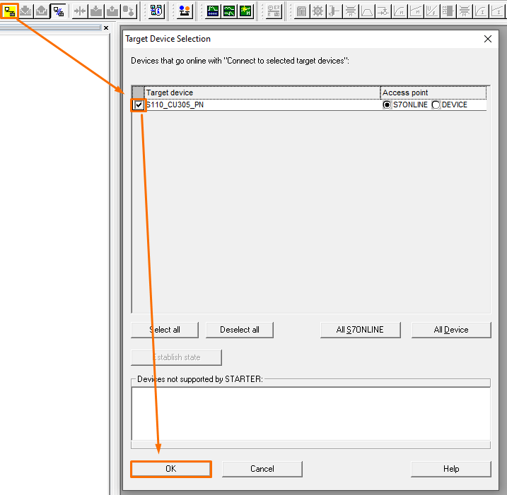
Now that most of the physical configuration is done go online with the proper target device.
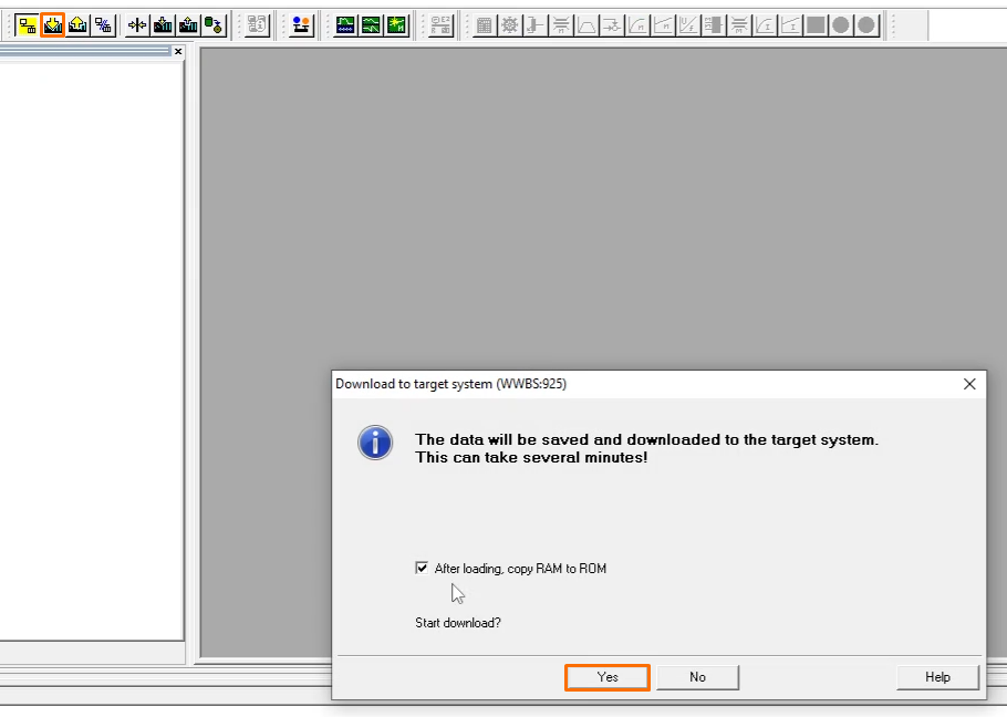
A pop-up should warn that the existing program differs from the project configuration, advising us to whether download our project to the drive or to upload the existing data from it. Proceed to download the recently configured project, and mark the checkbox below to load RAM(volatile memory) data to ROM(retentive memory).
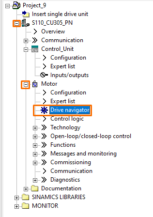
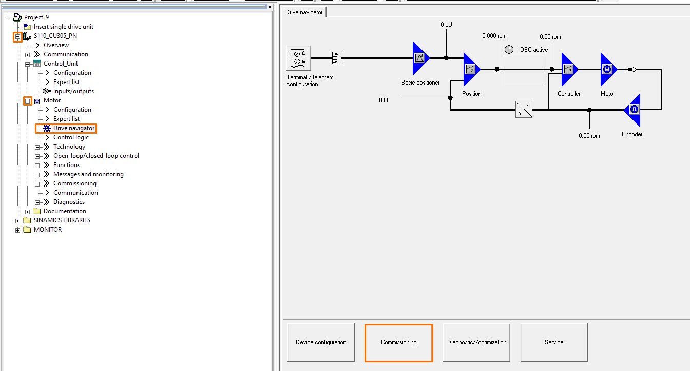
Every basic configuration is now finished, go under the Drive Unit tab in the project tree to find the Drive navigator.
Drive Commissioning from Control Panel
In the Drive Navigator window, it’s possible to monitor the main control block diagram in real-time. It’s beneficial to identify everything that’s happening behind the control operation of the drive. From the Drive Navigator, open up the Commissioning tool.
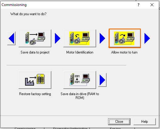
Select the function Allow motor to turn.
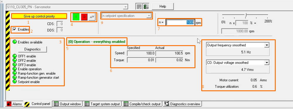
The control panel allows for real-time operation of the drive, directly from the Starter software. This functionality is extremely useful when commissioning drivers, which gives the developer the ability to run the motor with different speed and positioning setpoints, as well as monitors all the important data necessary for upcoming automatic operations, including positioning and advanced control tasks. The control panel covers the following operation and data monitoring:
- Assumes and Gives up the control priority: when the control panel has the control priority, the setpoint and control source defined in the drive is deactivated to enable operation strictly via the control panel.
- Enable: enable drive operation from the control panel.
- Enables available: shows all enabled status for monitoring purposes. This function is very useful for diagnostic errors when trying to run the motor.
- Start/Stop command: start and stop pushbuttons that command the configured setpoint(7) to the main control diagram and start the motor.
- Drive status: allows straightforward displaying of current drive status for diagnostics.
- Speed and Torque data: provides demanded(from setpoint) and actual(encoder) speed and torque for monitoring.
- Speed Setpoint: define the desired motor velocity for the start/stop command(4).
- Additional parameters: additionally, it’s possible to configure up to two additional parameters for monitoring during motor operation.
- Control type: select the control type to be utilized in the control panel, according to the control mode and function modules configured in the drive.
Speed Control Commissioning
To operate the speed control from the control panel, follow these steps:
- Assume control priority.
- Enable drive operation from the control panel.
- Set the desired speed setpoint. It’s recommended to run at an extremely low speed to ensure everything is fine in the mechanical system. Be careful when commissioning drivers in real process plants. If desired, enter a negative setpoint.
- Start the control operation on the green push button.
Positioning Control Commissioning
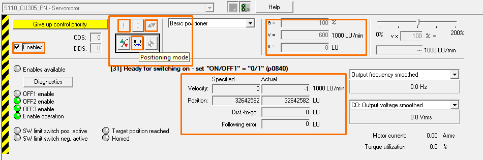
To operate the positioning control from the control panel, follow these steps:
- Assume control priority.
- Enable operation.
- Activate positioning mode.
- Set desired velocity (v) and accelerating setpoints (a).
- Start the motor on the green push button.
- Set destination position (relative positioning is recommended for commissioning). If reverse positioning is desired, it’s possible to set negative positioning setpoints.
- Start the positioning task.
Conclusion
Commissioning drivers and servo drivers is a vital skill for every automation professional. Sinamics Starter provides an intuitive and adaptative environment for driver configuration, controls development, and driver commissioning. It enables you to commission not only a regular speed controller but more complex function modules and control types.
This tutorial taught you the basics of commissioning drivers and servo drivers using the Siemens Sinamics Starter software.