The Complete Practical Guide to Siemens Tia Portal Programming

Introduction
TIA Portal is a software and tools package developed by Siemens, which aims to integrate multiple development tools for automation devices from the unification and remodelling of preexisting software such as Simatic Step 7, Simatic WinCC, and Sinamics Starter. The environments are responsible for programming, developing, and configuring Siemens PLCs, HMIs, and frequency inverters. The user's programming logic in TIA Portal follows a structure of blocks, a facilitating agent for the development, maintenance, and diagnostics of machines and industrial processes when developed in a structured and organized way.
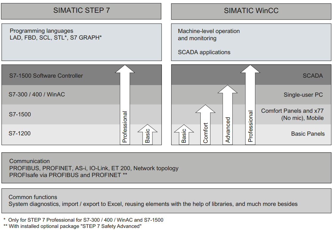
Step7 is used to program PLCs of the S7-1200, S7-1500, S7-300, and S7-400 families. WinAC and the latest S7-1500 Software Controller are alternative controllers for industrial computers. The available programming languages are ladder, FBD (Function Block Diagram), SCL (Structured Control Language), STL (Statements List), and S7 GRAPH. The Development of HMI screens in WinCC is applied to supervisory systems on computers, isolated or SCADA, and Basic, Comfort, and Mobile operational panels. Profibus, PROFINET, and AS-I (Actuator Sensor Interface) communication protocols. For communication with PLCs, it is worth mentioning the existence of CMs (Communication Modules) with functions to establish communications in different industrial protocols, such as Modbus and CANOpen. The Figure below gathers the main features for SIMATIC STEP 7 and SIMATIC WinCC.
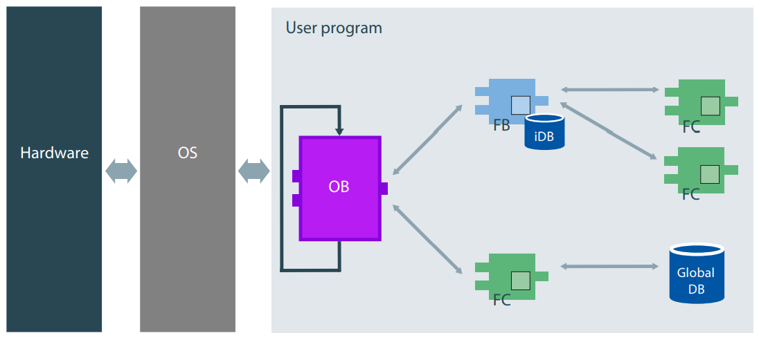
The monitoring of plant status and control of its actuator elements is done by devices connected to the controller's hardware. An operating system acts as an interpreter agent for the algorithms to run. PLC operating systems are responsible for translating logical instructions to the hardware according to the user program and hardware configuration of the PLC.
The controller programming is based on an architecture segmented into the blocks OBs (Organization Blocks), FCs (Functions), FBs (Function Blocks), and DBs (Data Blocks).
Understanding Organization Blocks in Tia Portal
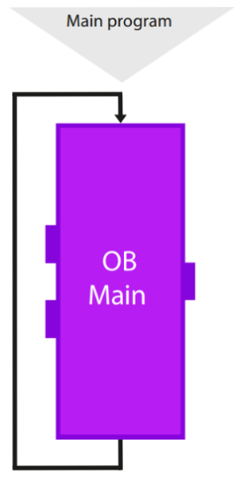
Organizational blocks are closely linked to program execution cycles and interrupts, as their execution is linked to previously defined triggers, such as a time interval or hardware failure detection. The OB1, or simply main, is essential for the initialization and sequential scanning of the calls of the blocks corresponding to the implemented code, except for other OBs, because it is a cyclic and continuous execution block. According to the representation of the Figure, the program execution starts with the contents of OB1 linearly and synchronously, codes from left to right and from the beginning to the end of the block. At the end of the main, the CPU resumes the execution of the code from the start and this process repeats indefinitely.
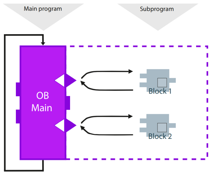
Although the user creates several blocks of functions and data, the PLC will only execute the dictated instructions and in the stipulated sequence through OB1. The Figure below demonstrates the creation of subprograms as evidenced by the block calls, which may have nested calls.
Since the reproduction of instructions in the main function depends on the processing of all assigned functions, its cycle time may vary with the state of the plant and any unanticipated programming conditions. Therefore, to avoid logical crashes or to guarantee the cyclical execution with a continuous activation period of a certain logical treatment, the Cyclic Interruption OB is recommended.
Cyclic Interrupt blocks are also executed cyclically but with a predefined time interval between executions when creating the block.
Thus, every 100ms, the current processing is interrupted so that the instructions contained in the Cyclic Interrupt block are carried out.
Understanding Functions (FCs) in Tia Portal
FCs compress the algorithm and return values to the variables defined as output, according to the input variables and the inspection performed inside the block.
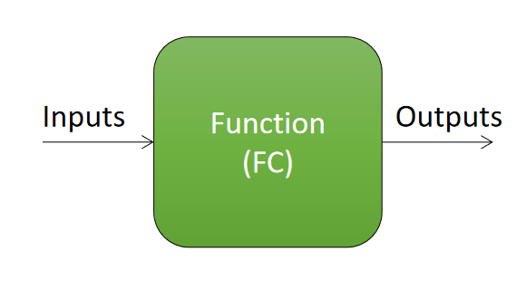
The local variables declared in FC and their characteristics can be of type In (input), Out (output), InOut (input and output), Temp (temporary), or Constant (Constant).
- Input: Input parameters of the function. It is essential to differentiate the states of different calls to the same function;
- Output: Output parameters of the function. It is essential to differentiate the actuation of different calls to the same function;
- Input and Output: Parameter that can be assigned as input and output at the same time. Useful for mitigating writing errors to input parameters;
- Temporary: Temporary variables that are allocated to a random space of CPU memory when starting the block and overwritten at the end of it, without the possibility of retention or global referencing;
- Constant: These are temporary variables whose values are fixed and defined in their declaration.
Understanding Function Blocks (FBs) in Tia Portal
Below we see the simplified diagram of the FBs, which have the same structure and function as the FCs, with the addition of the creation of iDBs (instance Data Blocks) related to each FB call.
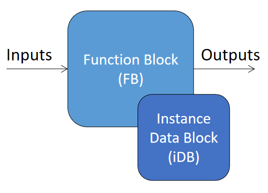
The variables supported in FC are also available for FB, but FB has one more type, called static. Variables of type static are retentive memories stored in the CPU's non-volatile memory that can be referenced throughout the program (they are global). When a FB is called in a programming routine, it is necessary to assign a DB instance to that call is necessary. Thus, different calls of the same FB have different memory spaces.
The Figure exemplifies the use of multiple calls from the same FB. Assuming an FB named Motors, this call being in two different lines of code is assigned two unique iDBs related to its specific call. Thus, a static variable called Motor_On indicates the state of that motor, related to its DB.
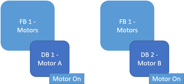
This way, it is possible to indicate that Motor A is connected through DB1 and that Motor B is connected through the variable allocated in DB2.
Understanding User Data Types in Tia Portal
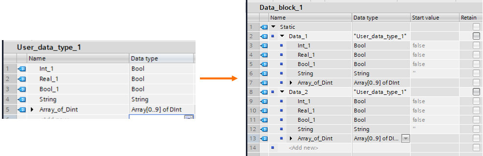
Besides the usual data types (Integer, Real, Boolean…) a variable in Tia Portal can be of a predefined data type called User Data Type. Its structure is mutable and can be composed of any combination of other data types available and arrays, for example. The use of UDTs helps in data structure organization and replication, making it easier to develop and diagnose programs.
Practical Example: Motors Actuation
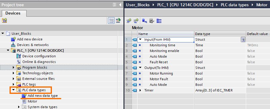
In this example, we will utilize Function Blocks, Functions, Data Types, and Data Blocks to address and optimize a simples task of actuating motors. At first, we should create a “Motor” data type, which includes all necessary information to be interchanged to the HMI.
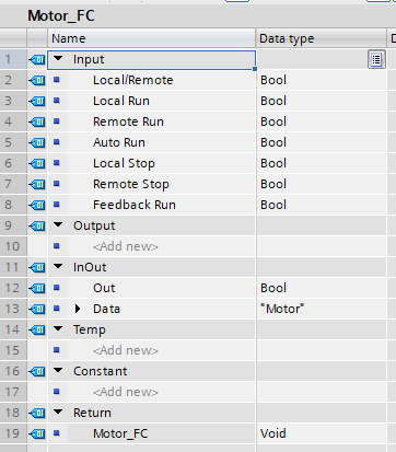
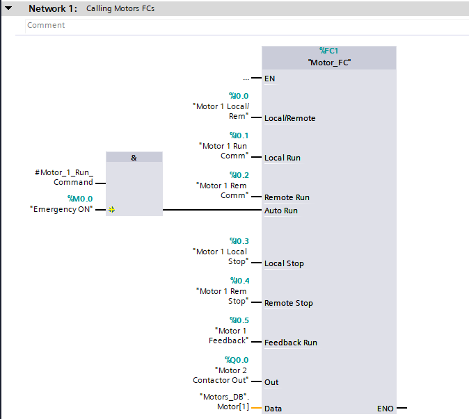
For our Motor Actuation FC, the inputs and outputs parameters should cover every physical equipment needed to operate the motor. Such as local and remote selectors, start and stop buttons, and motor running feedback sensor. The parameter “Data”, of the data type “Motor” we’ve just created and the output (to actuate the motor contactor) should be defined as InOut since we’ll be utilizing them both as input and output parameters over the program as well.
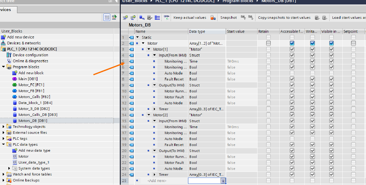
Our motor “Data,” of the data type “Motor”, needs to be stored in a global Data Block, being one variable of that data type for each motor to be operated. Therefore, it’s helpful to create an array of the data type “Motor” with the length equal to the desired number of motors.
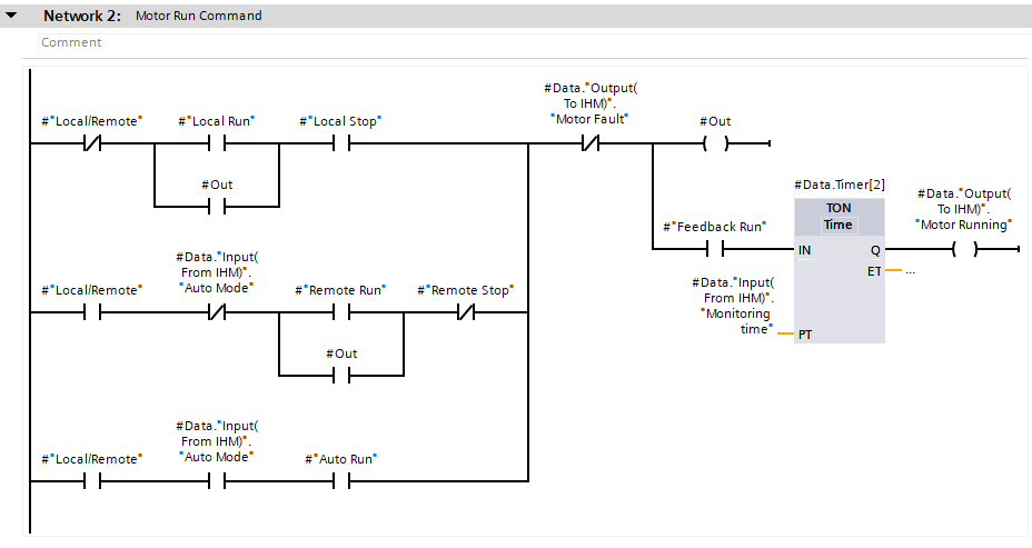
The function is able to monitor the feedback sensor and the motor output states to diagnose possible faulty scenarios. In the event of the feedback going on with no command from CLP to start the motor, we can identify a defective sensor or contactor. The second and third conditions are activated when the motor doesn’t move, even if the PLC command energizes the contactor coil, which can be diagnosed as an overload current trip, defective sensor, or defective contactor. The Motor Fault memory remains on until the operator requests a fault reset from the HMI.
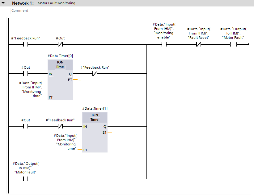
Once there’s no motor fault, our function treats the conditions to actually turn the motor on. The motor can be actuated from Local push-button inputs, Remote Manual on and off commands, and Remote Automatic commands. Once the motor and its feedback are evaluated for the predefined monitoring time, a feedback memory “Motor Running” is actuated for information and status display in the HMI.
Next, let’s link the first Motor Call to our first motor. All that’s needed to be done is to input the Input and input parameters corresponding to the equipment and signals resultant from that specific motor actuation.
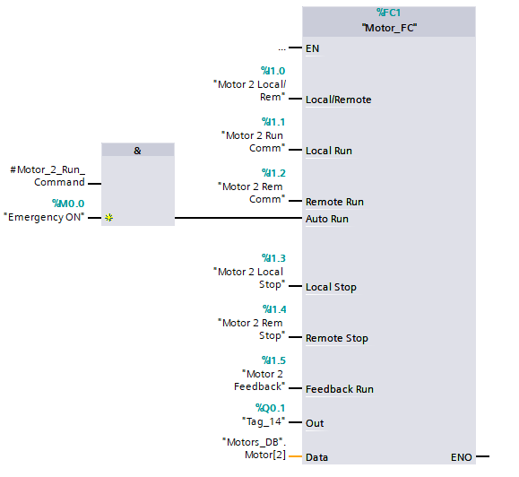
One of the prime advantages of using functions is replicating the logic for similar sub-systems. For example, to address the actuation of a similar (when it comes to process functionality) motor, it’s as easy as replicating the block call and inputting the parameters for the respective motor.
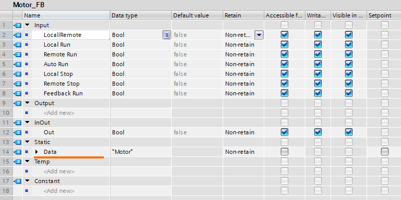
Another possible logical structure for the program would be to make use of a FB, instead of an FC block. This way, it wouldn’t be necessary to create a Data Block to accommodate the Motors Data, utilizing Statics tags(an Instance Data Block) from the calling environment associated with that specific motor. The FB parameter structure would be pretty similar, the only difference being the type of the parameter Data to be now defined as Static.
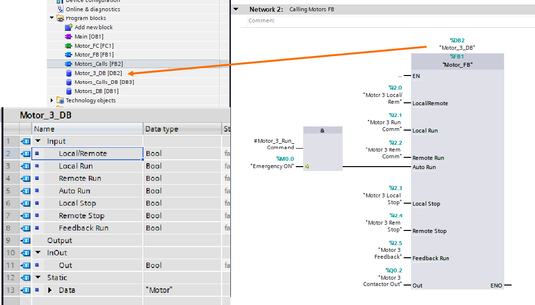
As soon as the Motor FB is dragged into the user program to create the Motor 3 Call, a wizard is initialized to help create a Data Block to be associated with that FB call.
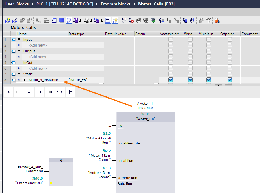
It’s also feasible to link the DB to a multi-instance Data Block, defined as a tag of the “Motor_FB” data type in the FB “Motors_Calls” static parameters. This strategy comes in hand with certain program structures where multiple equipment and operations are fragmented into function blocks, making it easy for replication and memory organization, as it condensates all multi-instance DBs in a single DB from the original function call.
Frequently Asked Questions (FAQ)
What is TIA Portal, and why is it important for automation projects?
TIA Portal (Totally Integrated Automation Portal) is Siemens' unified engineering software used for configuring, programming, and commissioning industrial automation systems. It integrates multiple engineering tasks — PLC programming, HMI development, motion control, and network configuration — into a single environment.
Why it matters:
- Efficiency: Reduces engineering time through an integrated workflow.
- Consistency: Centralized project management minimizes errors and data mismatches between PLCs, HMIs, and drives.
- Scalability: Supports everything from small standalone machines to large, complex manufacturing systems.
- Industry Standard: Siemens automation products are widely adopted globally, especially in manufacturing, food & beverage, automotive, and pharmaceuticals.
Learning TIA Portal not only helps with immediate project delivery but also enhances your long-term value in the automation industry.
Which Siemens PLCs can I program using TIA Portal?
TIA Portal supports programming of several Siemens PLC families, including:
- S7-1200 series: Ideal for compact automation applications (small machines, OEMs).
- S7-1500 series: Advanced, high-performance PLCs for complex, high-speed control systems.
- S7-300 and S7-400 series (with compatibility packs): Legacy support for upgrading existing installations.
- ET 200SP CPUs: Modular, decentralized automation systems.
- LOGO! Controllers: (Limited programming support through specific versions).
Important note:
When working with older PLC models (e.g., S7-300), confirm your TIA Portal version compatibility, as some newer versions phase out support for legacy hardware.
Can I use TIA Portal without real hardware for learning and testing?
Yes!
You can fully simulate your projects using PLCSim, Siemens' integrated simulation software included with TIA Portal.
With PLCSim, you can:
- Test ladder logic, structured text (SCL), and function block diagrams.
- Simulate PLC hardware behavior (digital and analog inputs/outputs).
- Interact with HMI screens if you’re using WinCC inside TIA Portal.
- Validate sequences and troubleshoot logic without risking equipment damage.
Pro Tip: Make sure your TIA Portal version includes PLCSim Basic or PLCSim Advanced (for more complex simulations like virtual networks).
Learning through simulation is highly recommended before downloading to real hardware, especially for beginners.
What programming languages are available inside TIA Portal?
TIA Portal supports multiple IEC 61131-3 programming languages, allowing engineers to choose the most suitable one based on the project:
- LAD (Ladder Diagram): Visual, relay-logic style programming — most popular in North America.
- FBD (Function Block Diagram): Visual, flowchart-like — preferred for logical sequences.
- SCL (Structured Control Language): Text-based, similar to high-level languages like Pascal/C — powerful for loops, calculations, and complex data processing.
- STL (Statement List): Assembly-style, low-level programming — mainly used for legacy support.
- GRAPH (Sequential Function Chart): Ideal for step-by-step process control (available with additional licensing).
Choosing the right language depends on the application, the team’s background, and maintenance considerations. For example, SCL is often preferred for complex math or when working with arrays and structures.
What are common mistakes beginners make when programming in TIA Portal?
Here are some frequent pitfalls new users face:
- Hardware Version Mismatch: Selecting the wrong firmware version during hardware configuration leads to download and compile errors.
- Unorganized Tag Naming: Using default names like "M0.0" instead of meaningful tags like "StartButton" makes future troubleshooting extremely difficult.
- Incorrect Block Structure: Not separating code into logical function blocks (FBs and FCs) results in bloated, hard-to-maintain programs.
- Forgetting to Download Both Hardware and Software Changes: Sometimes only software changes are downloaded, causing hardware settings to remain outdated.
- Poor Error Handling: Skipping status checks (e.g., diagnostics for communication modules or drives) leads to unexpected run-time issues.
Tip:
Always plan your architecture — even for small projects — and document every major step inside your project notes or software comments.
What is the difference between an OB, FC, and FB in TIA Portal?
- OB (Organization Block):
The main scheduling blocks that control execution flow.
Example: OB1 is the default cyclic execution block that continuously runs while the PLC is in operation. - FC (Function):
Code blocks that perform specific tasks but do not retain memory between scans.
Example: Calculating the speed of a conveyor based on a sensor input. - FB (Function Block):
Similar to FCs, but retain data internally through instances.
Example: Motor control blocks that keep track of start/stop status across scans.
Understanding how and when to use each is critical to writing modular, maintainable code.
How do I troubleshoot communication problems between TIA Portal and my Siemens PLC?
If TIA Portal cannot connect to the PLC, check the following:
- Network Configuration:
Make sure your PC is in the same subnet as the PLC (example: 192.168.0.x series). - Correct Interface:
Verify the correct PG/PC interface is selected under “Online Access.” Ethernet (TCP/IP) is common for S7-1200/1500 series. - Firewall Settings:
Disable or adjust firewall/antivirus programs that may block communication ports (e.g., TCP port 102). - Device Firmware Compatibility:
Ensure the PLC firmware is supported by your installed version of TIA Portal. - Cables and Switches:
If you're using unmanaged switches or older Ethernet hardware, check cable integrity and port settings.
Tip:
Use the "Accessible Devices" tool inside TIA Portal to scan your network and verify device presence.
Can I upgrade a TIA Portal project to a newer version?
You can upgrade projects to a newer TIA Portal version, but you cannot downgrade them once upgraded.
Example:
- A project made in TIA Portal V15 can be upgraded to V17.
- A project created in V17 cannot be opened directly in V15.
Upgrade process:
- Open the project in the newer version of TIA Portal.
- Accept the prompt to upgrade.
- Review any hardware compatibility warnings, as device catalogs sometimes change between versions.
Best Practice:
Always back up your original project file before upgrading.
Is there a free version of TIA Portal available?
Siemens offers a trial version of TIA Portal that is fully functional for 21 days.
It includes access to PLC programming, HMI configuration, and basic simulation tools.
Where to get it:
- Download from Siemens' official website (after creating a free account).
Limitations after trial:
- Some features like PLCSim Advanced and complex network simulation might still require paid licenses.
- You’ll need a valid license to continue using the software commercially beyond the trial period.
Conclusion
There are many features inside the TIA Portal development tool that facilitates development, data structurization, maintenance intervention, and scalability of industrial process and equipment. Even though there are many different ways to accomplish the same results in PLC programming, it’s always beneficial to seek the most efficient one.
