HMI / PLC Fundamentals - Syncing & Sending PLC Time to HMI Terminal
Introduction
Time synchronization is an important step for displaying the right information to the machine operators, SCADA based data logging and for general accessibility. Creating this link between an HMI and PLC system is not as straightforward as one might think. That being said, time synchronization becomes quite simple after you’ve done it once.
We will be exploring this process between a CompactLogix L24ER processor programmed in v30 Studio 5000 and an HMI running v5.10 FactoryTalk View ME application. Through this process, we will also create a UDT for our structure and send it over as a regular tag in order to use it independently from the time logged by the HMI terminal.
UDT Time Structure in Studio RSLogix 5000
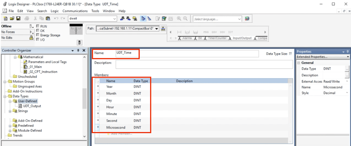
The UDT structure will support all of the registers which will store the current time on the Programmable Logic Controller (PLC). This structure can be used inside the Studio 5000 program as well as through the HMI application. It’s also labeled intuitively, so the registers are self-explanatory.
Note: it’s important to place the registers in this exact order as the copy instruction will populate the UDT in this same order. If this order isn’t followed, the data will not match the info placed inside.
Here’s a snapshot of the finalized UDT:

In the UDT above, we have 7 distinct members all of the type DINT:
- Year
- Month
- Day
- Hour
- Minute
- Second
- Microsecond
GSV – Get System Value Instruction
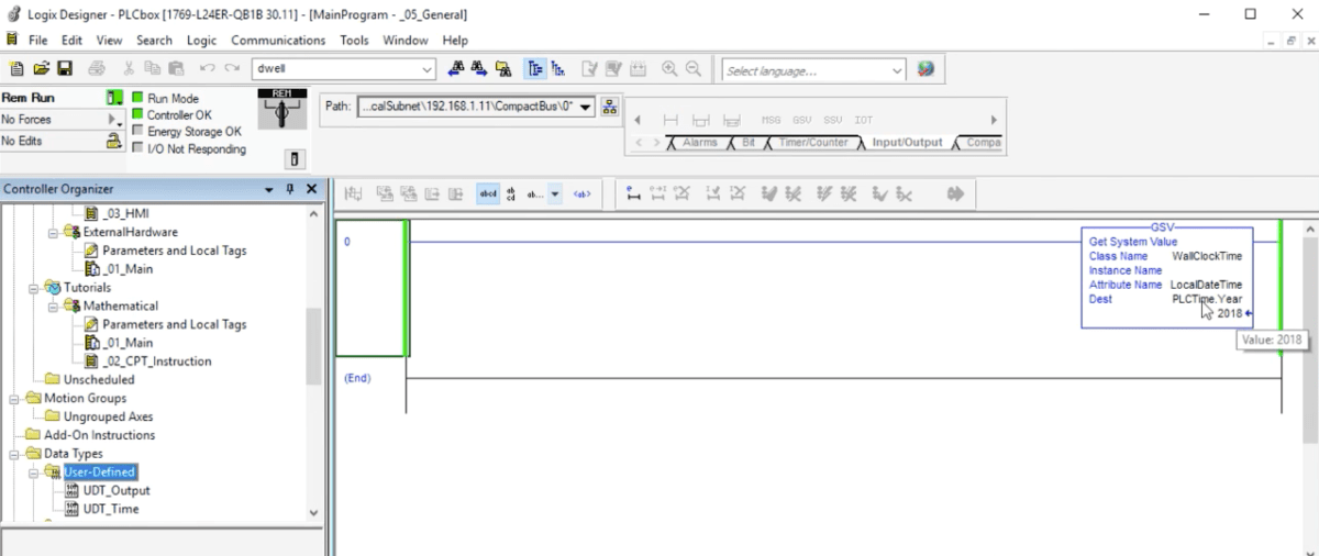
The Get system Value, or the GSV, instruction is used to retrieve the data from our PLC registers. This instruction is similar to what a MOV instruction accomplishes but will be primarily applied to hardware-based registers which you can’t get otherwise.
To retrieve the current time settings from the PLC, we need to specify a class name of “WallClockTime” as well as a destination register which is based upon the UDT we created before. In this program, this register is labeled as “PLCTime”. Furthermore, a starting register must be specified to load our data. In this case, it’s the “.Year” designation. All of the registers will be loaded.

Setting HMI Time through Global Connections
Now that we have our structure and the controller is in Run Mode, we can create the link from the HMI. This process requires us to add the PLC to the Communications tree of the HMI. This process is covered in one of the earlier tutorials: HMI to PLC Tag Based Link Tutorial.
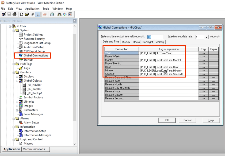
Once the link is created, we need to open the “Global Connections” menu and add the appropriate tags from the PLC UDT structure to the HMI cells. Here’s what the outcome looks like:

Displaying PLC Based Time directly on HMI Screens
Although the method above will synchronize the time on the HMI terminal, it’s preferable to skip this procedure altogether and format the time based on what it’s set to on the PLC. This practice allows the engineer to keep the time in one place and display it exactly as it is on the main system. Furthermore, in most cases, you will be relying on the PLC time for your SCADA system thus making it the most important asset.
This is accomplished simply by creating a numeric display tag sequence which retrieves the same tags we’ve defined above. Although the sequence of numeric displays requires some tweaking, it allows one to use it all over the place once it’s properly implemented. Here’s a quick design of the said system. Each numeric display is properly formatted and links back to the PLC tags we’ve described above.

Conclusion
Synchronizing the time between the PLC and the HMI can be tricky, but is very important for anyone working with control systems. The steps outlined above will synchronize the time between a PLC system running RSLogix or Studio 5000 and an HMI which is designed through FactoryTalk View Studio ME.


