How to Exchange Data Between Siemens PLCs and SCADA Using CIP Protocol

Introduction
Siemens PLCs frequently communicate with other PLCs, peripheral devices, and advanced control systems, including Supervisory Control And Data Acquisition (SCADA) and Manufacturing Execution Systems (MES). This communication is essential for controlling various components within an industrial automation environment. Effective communication ensures that data is accurately and reliably exchanged between devices, enabling seamless operation and monitoring of processes.
To achieve this level of integration and interoperability, all involved parties must use the same communication protocol. Using a standardized protocol ensures compatibility, reduces the potential for communication errors, and simplifies the configuration and maintenance of the system.
Figure 1.1 shows a basic configuration for using CIP/PCCC as the protocol for executing this data exchange, as demonstrated by the following application example.

Prerequisites
What you will need to follow along with this tutorial:
- You need to install the TIA Portal software on your personal computer. Although this tutorial refers to version 19, rest assured that other versions of the TIA Portal will work just fine.
- Prior familiarity with the 'Configuring CIP as the communication method in Rockwell Studio 5000 software' will prepare you to engage more effectively in this tutorial.
Principle of Operation
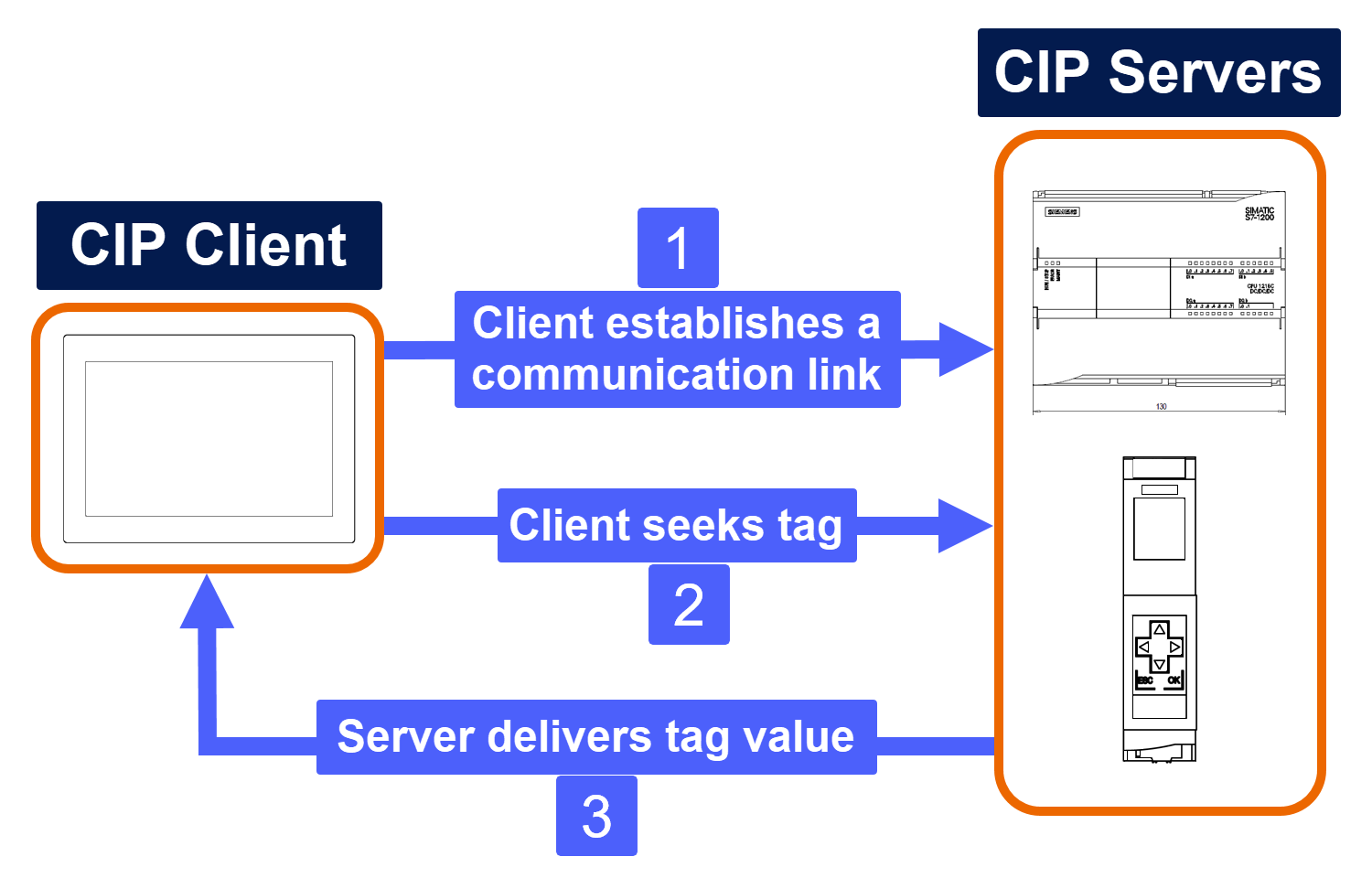
The Client-Server model governs how communication occurs with CIP/PCCC. The Siemens PLC is responsible for the CIP server within this application. The Siemens PLC provides the CIP client with process data by implementing the designated function block.
WinCC is used in this application example to set up the CIP client, offering several options for connecting to Siemens PLC and external systems through various communication drivers. This example, specifically, utilizes the EtherNet/IP driver.
The CIP client initiates the process by establishing a connection with the CIP server and then requests the necessary data to be displayed on the screen. Additionally, this application allows for modifying process values within the Siemens PLC, enabling real-time adjustments and control over the processes managed by the PLC.
Engineering and System Setup
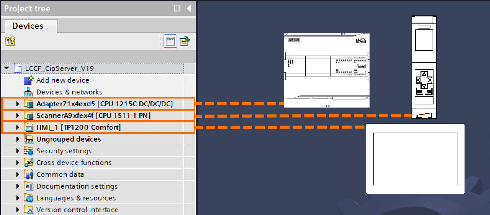
Open the TIA Portal software on your computer. Once the software is running, start by creating a new project. After initiating the new project, proceed by configuring the hardware settings necessary for the application example provided in this tutorial.
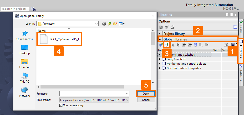
Download the CIP Server library from this link. Go to the right-hand side of the software environment and open the ‘Libraries’ task card. Expand the Global Libraries tab and click the Open Global Library icon to open its window. When the pop-up window opens, locate and select the downloaded CIP Server library.
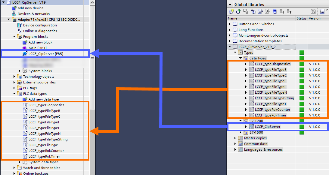
After you have inserted the CIP Server library, drag and drop the relevant data types and the associated function block into their designated folders within the Siemens PLCs. It ensures that all necessary components are correctly organized and integrated into the system for proper functionality.
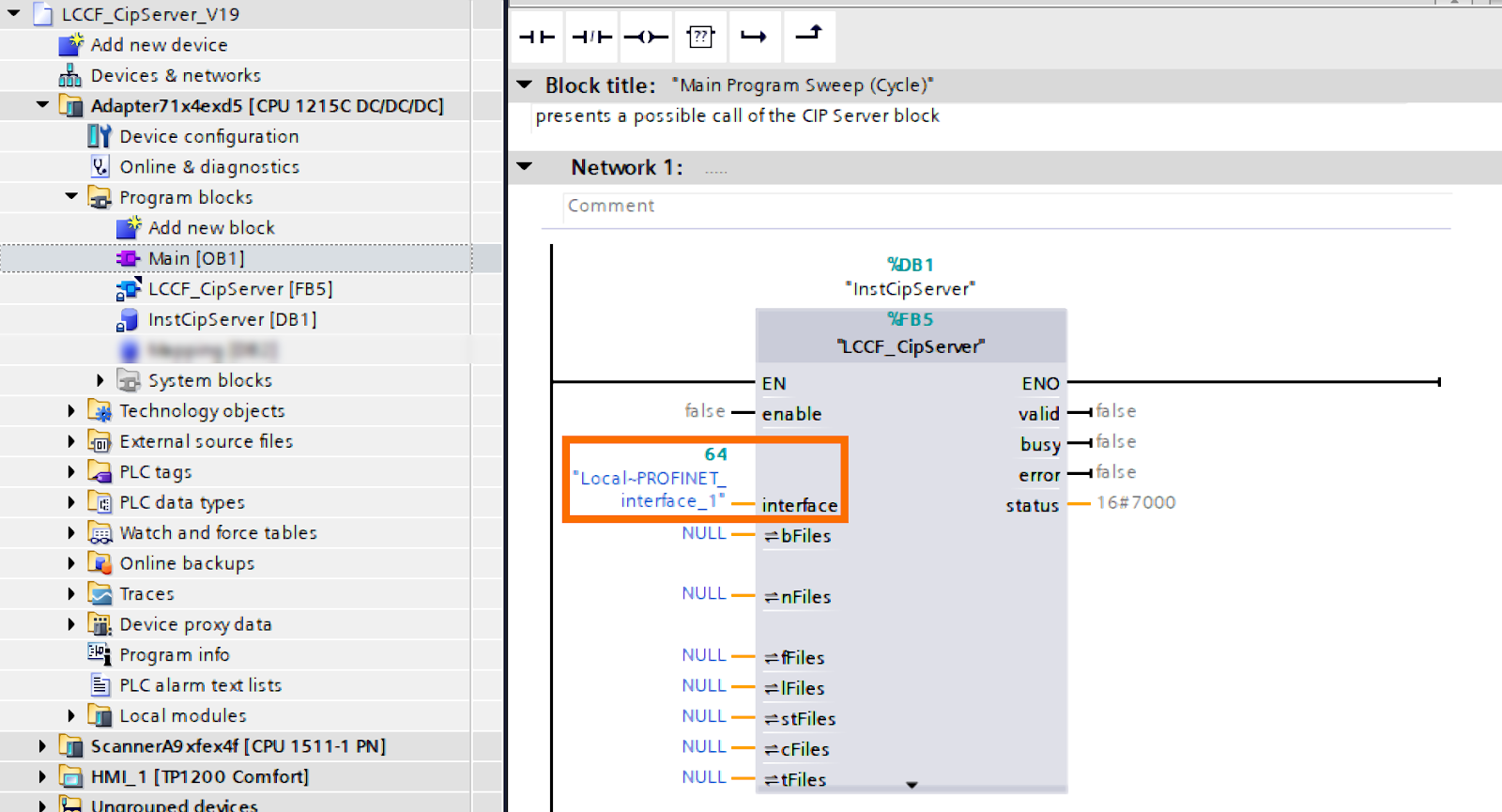
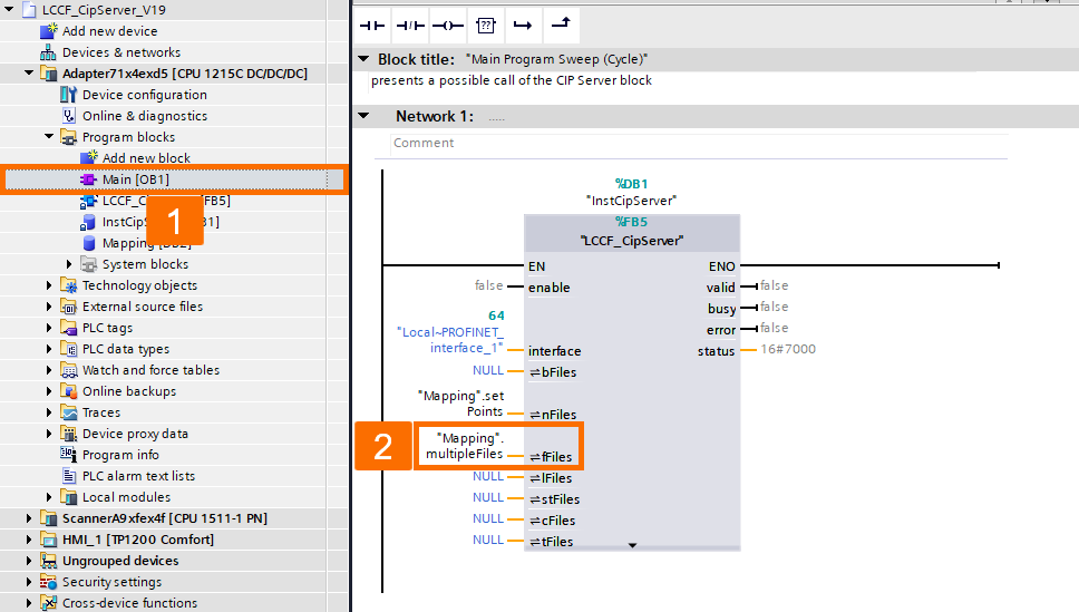
Access the main organizational block. The programming interface will then display a blank rung. Proceed by inserting the CIP Server function block into the Main [OB1]. A pop-up window will appear requesting the instance data block. Assign it the name ‘InstCIPServer.’
![Figure 3.4: PLC and SCADA communication - Calling CIP server function block into the Main [OB1]](https://cdn.prod.website-files.com/63dea6cb95e58cb38bb98cbd/66c4910b2c0e6d48efe2e3fd_AD_4nXcKx4-Ce-y2uJgYVl-KdfCmrjq4eGzwudovYjGszvK1SNGbiODLQ5gX7qCxv54R6tmmzYkIOuYDxDlFGlWyVeqyvG4lEm7hB5bnmNKd4Z3jv9lUzQ_hTlbIQjjdAr-dGvvlgNdMx67ja9vDrxvdKgfLmANTExn-dVICkbjQYg.png)
To facilitate communication, use the CPU's embedded PROFINET Interface by assigning the precise parameter to the block call. The result of configuring the PROFINET Interface with the appropriate settings is that you enable efficient and accurate data exchange between the Siemens PLC and other connected devices.
Because the internal addressing method used by Siemens PLC for process tags does not match the requirements of the PCCC services, it is necessary to implement a mapping procedure. This mapping aligns the Siemens PLC address structure with the format expected by the PCCC services, ensuring accurate communication and data exchange between the systems.
In the mapping, there might be multiple files of a particular type. Each file's size is pre-established and unchangeable. Here are the instructions for setting up the mapping.
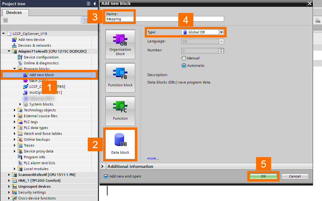
Generate a brand-new global data block (DB) and assign it the name 'Mapping.' Once the data block has been created, it will automatically open in the DB editor for further configuration and editing.
Set up a DB variable identified as 'Type N.' A fresh variable, structured with 100 elements and including a file number variable, will be given to you. Specify the file number you want to use. The default for N-files is set to 7. Next, compile the database you've created.
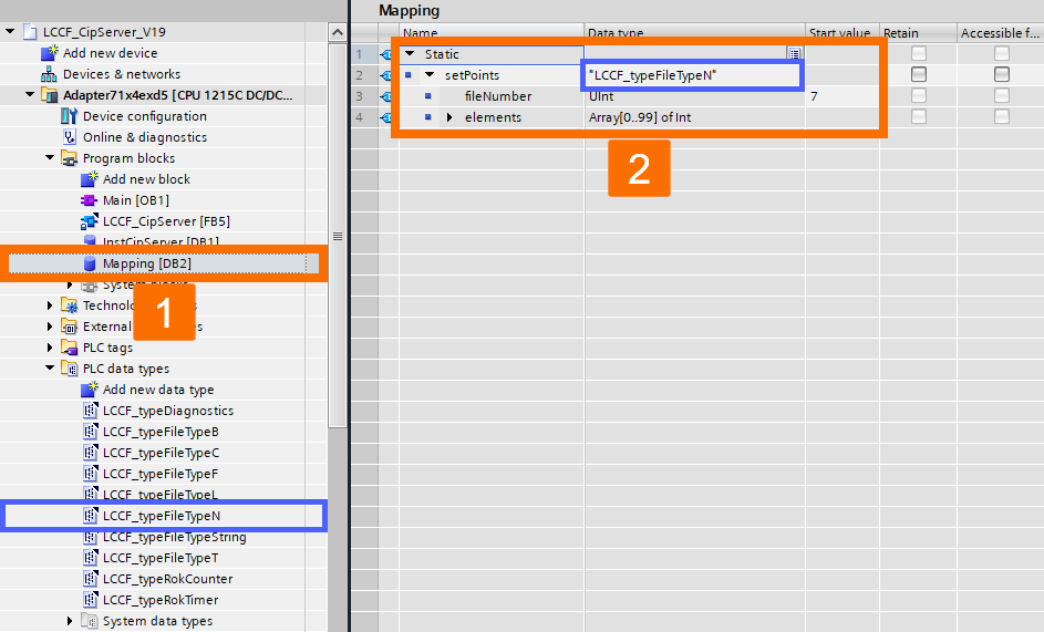
Ensure the variable is allocated to the CIP Server block with the 'nFiles' formal parameter. Any different assignment will trigger an error during server startup, thus completing the single file parameter assignment.

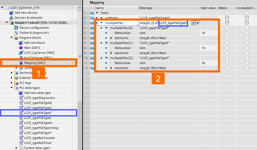
If you have several files, you can allocate an array of them to the corresponding formal parameters. The memory capacity of the CPU module is the only factor limiting the maximum size of a file array since the CIP Server block doesn't impose restrictions.
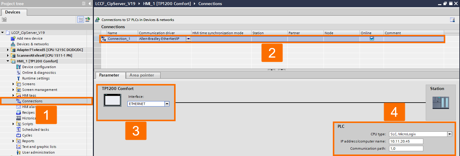
Configuration of the CIP client is required before it can retrieve the mapped data. Navigate to the Connections section of the HMI panel. The editor for Connections will display. Introduce a new Allen-Bradley EtherNet/IP connection. Thus, a new connection by the name Connection_1 is formed. Adjust the connection configuration. Assign 'SLC, MicroLogix' as the CPU type. Assign the IP address to match the S7-1200 Siemens PLC IP. Keep the communication path set to: '1,0.' The connection now functions as an EtherNet/IP link with the CIP/PCCC protocol.
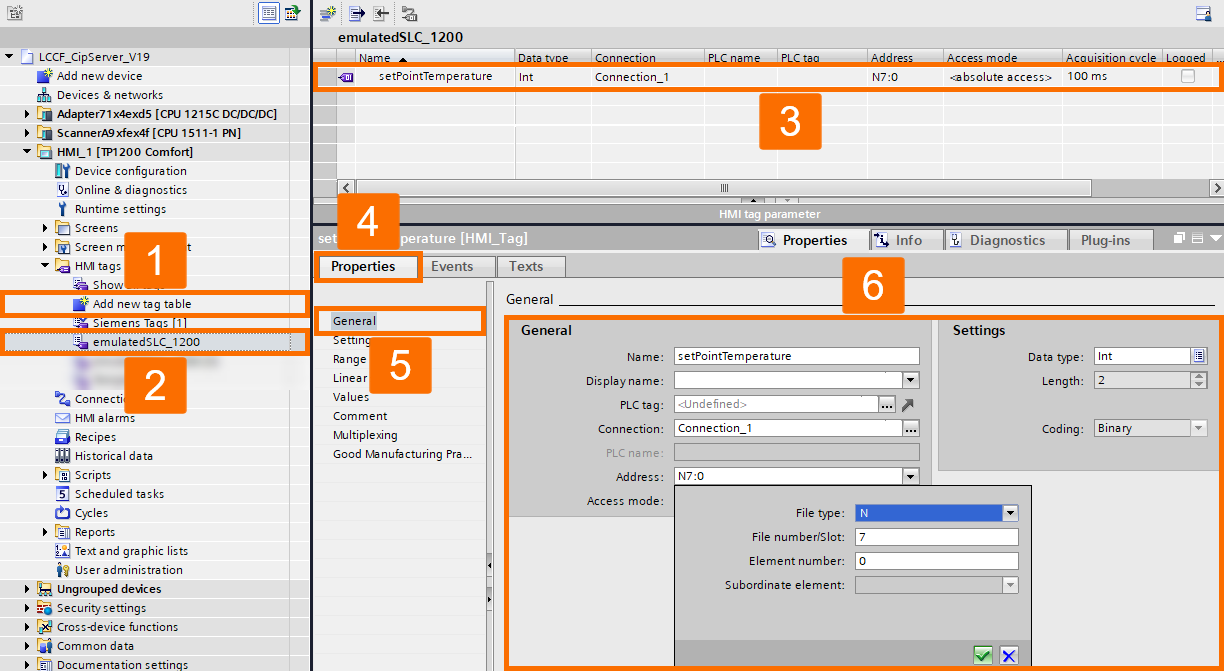
Establish a new directory for HMI tags through the emulated SLC connection. Name the newly created folder as 'emulatedSLC_1200.' Introduce new tags within the recently created directory. Set [N7:0] as the address. Select 'Connection_1' as the connection. Assign 'N' as the file type, '7' as the file number, and '0' as the element number.
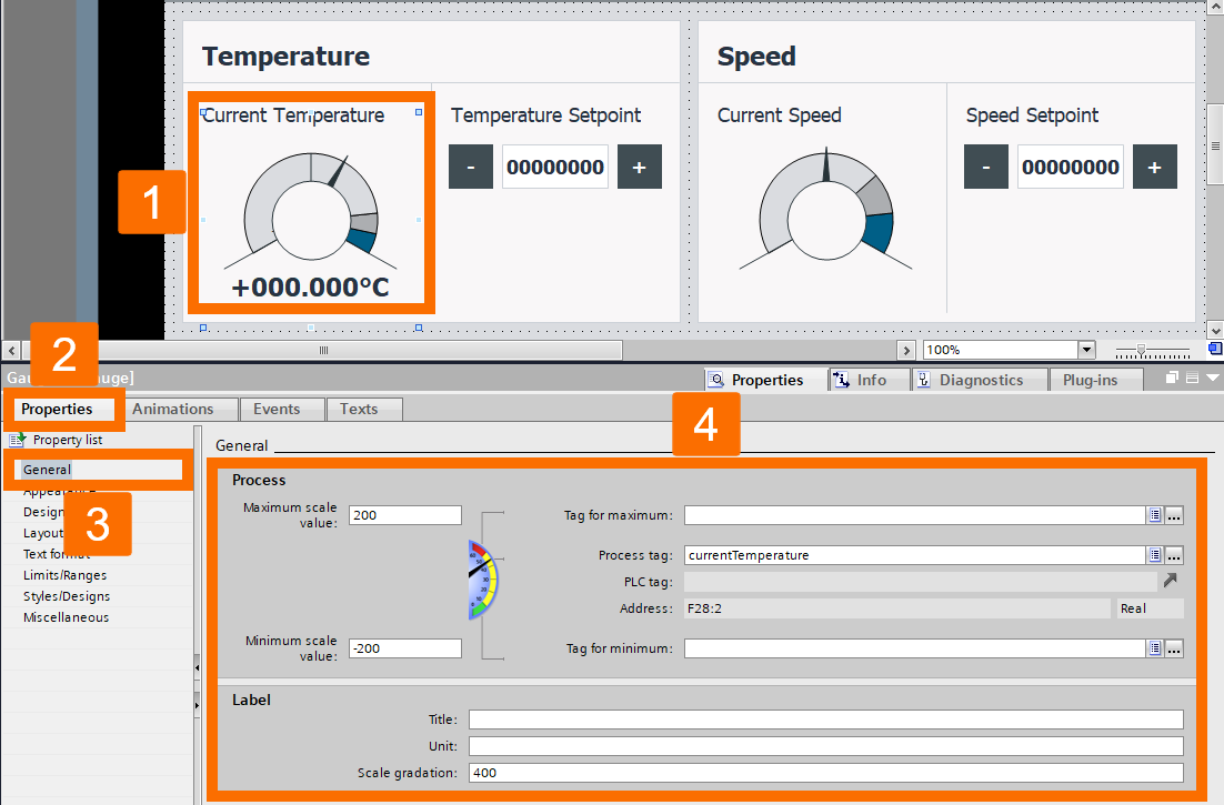
Carry out the prior step for other tags: speed setpoint, Integer type, with the address of N7:19, and current temperature, Real type, with the address of F28:2. The mentioned tags are currently available to be utilized in your application's screen.
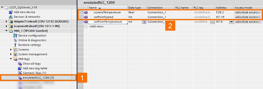
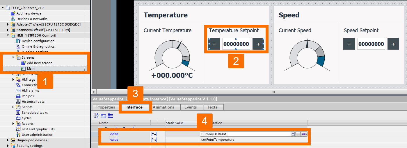
Develop your HMI interface and embed the tags into it. Without an S7 connection between the PLC and the Panel, as you've seen, it resorts to EtherNet/IP for reading and writing the variables in the PLC.

Execution and Testing
After downloading the PLC program to the PLC, proceed by activating the CPU module's RUN mode by clicking on the Start CPU icon located in the top toolbar. This action initiates the execution of the PLC program within the CPU module, ensuring that the system begins operating as configured.

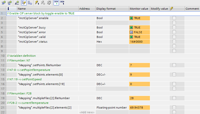
The CIP Server block is currently running and is set to IDLE mode without establishing any interaction with partners. For this setup, you must activate the CIP server, and the optimal method is to create a watch table and name it 'watch CIP Server.' Populate the watch table with variables based on your configuration settings.
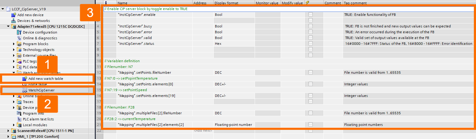
Ensure the 'enable' input of the CIP Server block instance is set to TRUE.
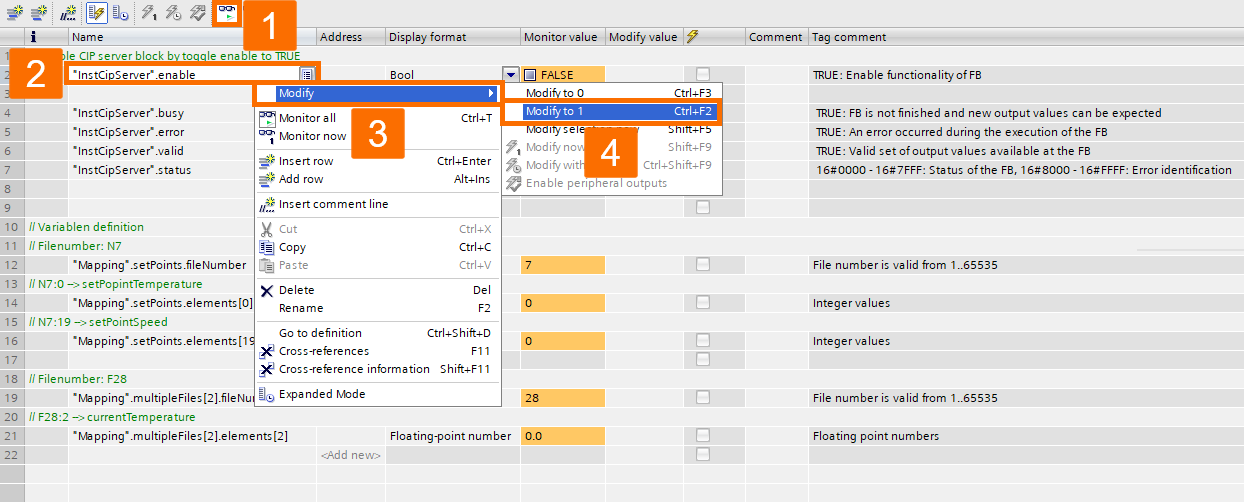
If the setup is correct, the status data will reflect busy and valid parameters marked as TRUE, the error parameter marked as FALSE, and the status parameter showing 16#0000.
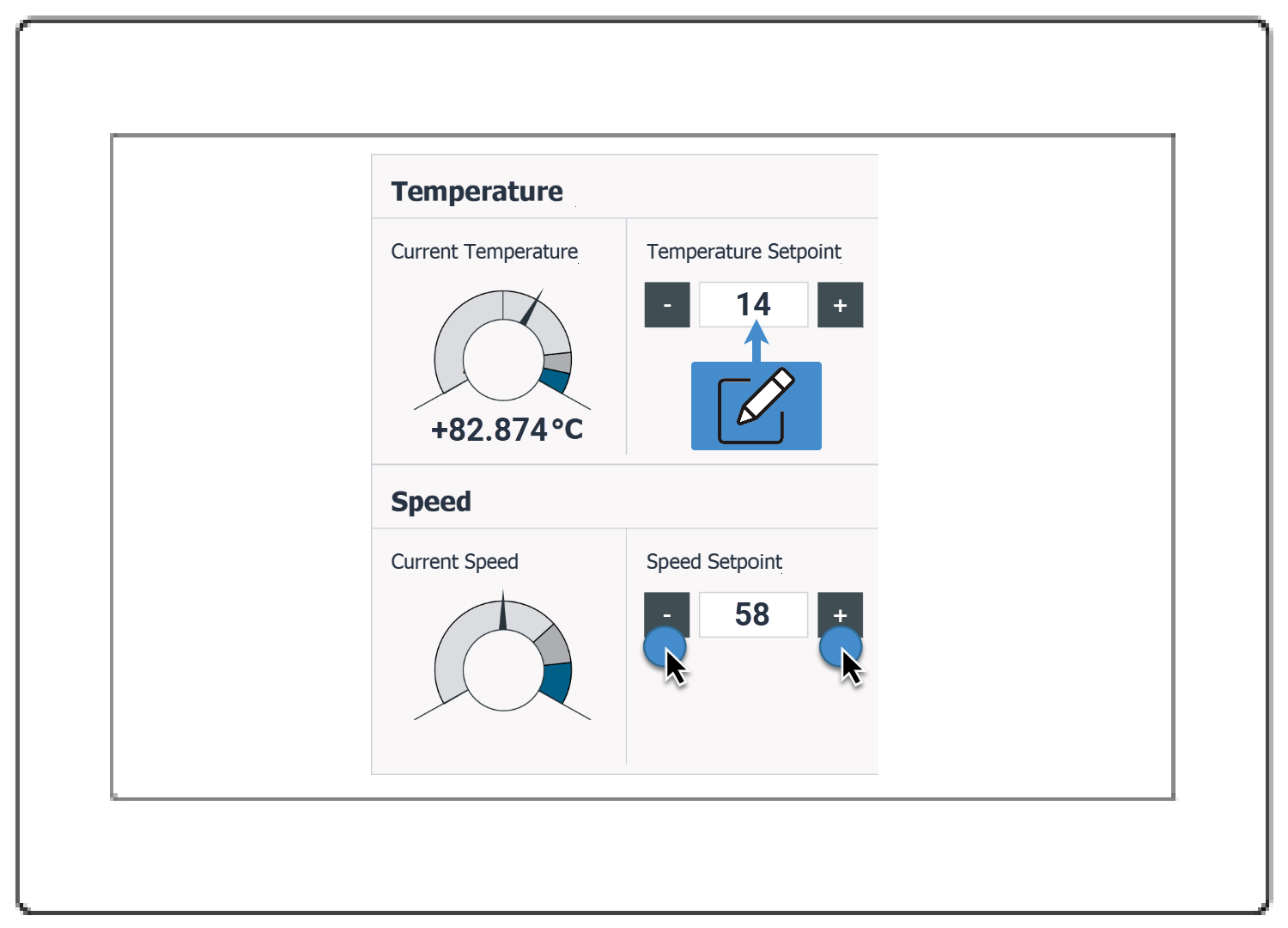
You may proceed to edit the values in the watch table. Confirm that the updates have been applied successfully to the WinCC Runtime Advanced or the Panel you worked with. The tags being read from the PLC are indicated by this communication.
Adjustments to values can be made in the active Simulation or on the actual hardware of the Siemens Comfort Panel. Look at the program to confirm that your edits are visible in the watch table since this reflects the communication's writing flow.
Conclusion
In conclusion, you learned how to set up and execute data exchange between Siemens PLCs and SCADA systems using the CIP/PCCC protocol. This tutorial guided you through the necessary steps, including software prerequisites, configuring the CIP server and client, setting up the communication mapping, and establishing EtherNet/IP connections. You also learned how to create and configure HMI tags and interfaces, download and run the PLC program, and verify successful communication and data exchange between the PLC and the SCADA system. With these skills, you can effectively manage and monitor Siemens PLCs using SCADA. Keep in mind that you're likely to see a Manufacturing Execution System (MES) on top of the SCADA
