Integrating EtherNet/IP Field Devices with Siemens PLCs

Introduction
PROFINET takes the lead as the most widely installed Ethernet-based fieldbus, with EtherNet/IP following closely. EtherNet/IP is notably prominent in numerous regions across the world. EtherNet/IP field devices are not inherently compatible with Siemens PLCs.
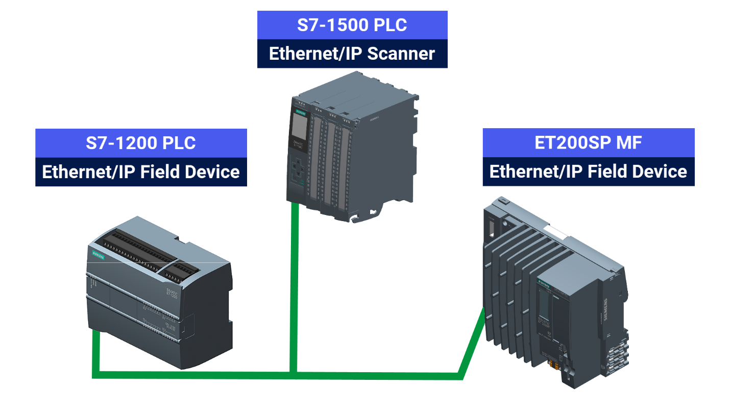
This tutorial explores how EtherNet/IP field devices can still function with Siemens PLCs, including the S7-1200 and S7-1500 series. The S7-1200 and the ET200SP MF function as EtherNet/IP field devices, with the S7-1500 responsible for handling them. In a different tutorial, we've covered working with PROFINET devices such as Servo Motors on TIA Portal.
The components of an EtherNet/IP network are the Scanner and the Adapter. Scanners, engaged in network monitoring, gather data like sensor readings from various field devices. These field devices are called Adapters.
Prerequisites
What you will need to follow along with this tutorial:
- You need to install the TIA Portal software on your personal computer. Although this tutorial refers to version 19, rest assured that other versions of the TIA Portal will work just fine.
- Prior familiarity with the 'Ethernet/IP Connection to ControlLogix Devices' will prepare you to engage more effectively in this tutorial.
- [OPTIONAL] If you're working with Allen Bradley systems, you can use RSLinx to set-up some of your devices on EtherNet/IP.
Principle of Operation
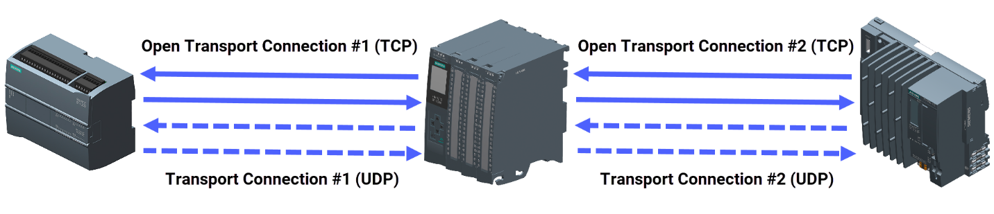
Using a TCP connection, the Scanner initiates the communication process. After associating the Scanner with Adapters, a transport connection is arranged for each Adapter. Upon success, the connection activates, and UDP datagrams facilitate data transfer.
Technical Setup
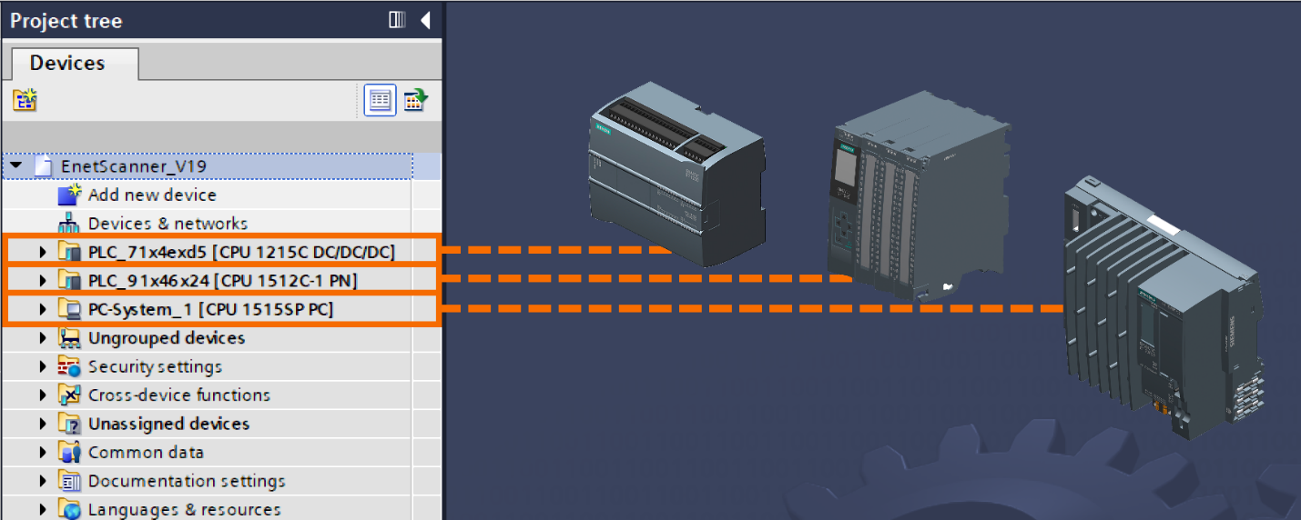
Launch the TIA Portal software. Begin by setting up a fresh project and continue by configuring the hardware required for your application example.
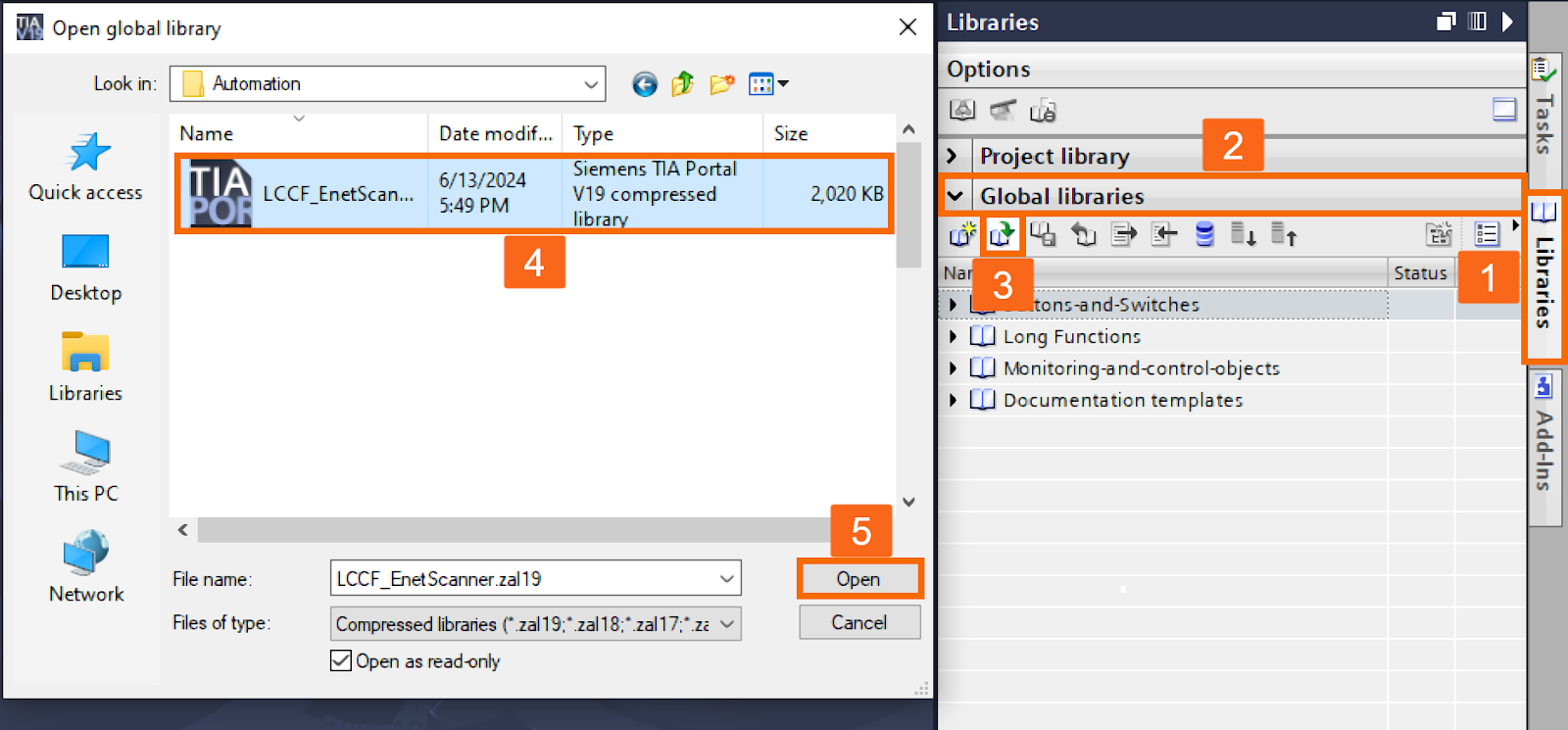
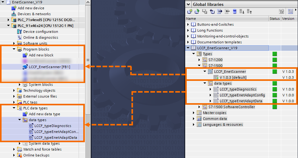
Download the 'Ethernet IP Scanner' library. Navigate to the 'Libraries' task card on the right, expand 'Global Libraries,' and use the 'Open Global Library' icon to load it.
Once the 'Ethernet IP Scanner' library is added, place the related function block and data types into their proper folders in Siemens controllers.
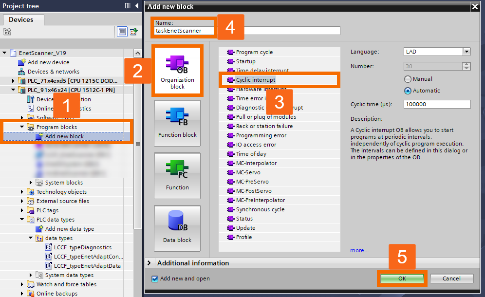
Also, consider creating a Cyclic Interrupt OB (OB30) for your project.
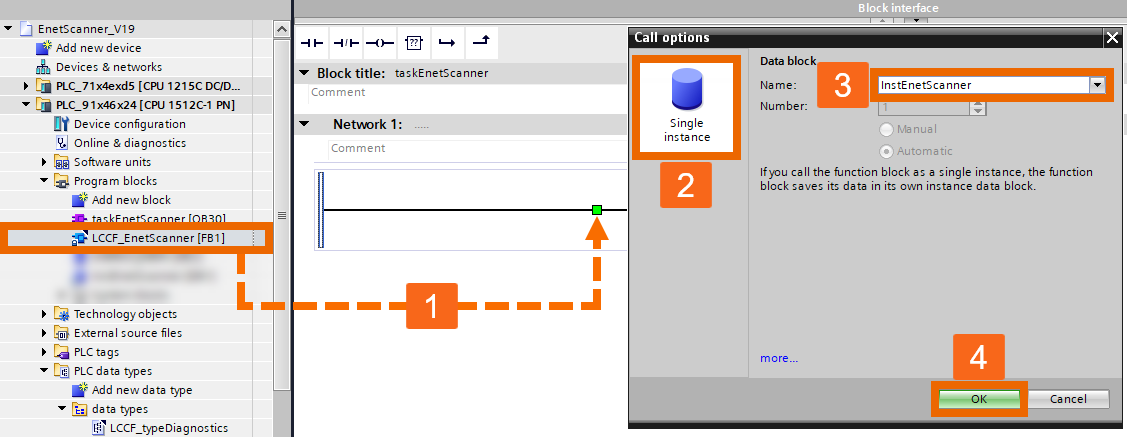
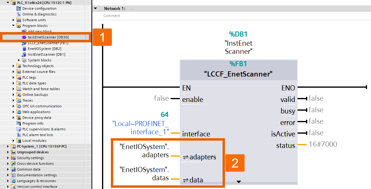
Once the Cyclic Interrupt OB opens in the editor, insert the 'Ethernet IP Scanner' function block into network 1. TIA Portal will prompt you to create an instance DB (data block). Choose a preferred name for the DB and confirm by clicking ok.
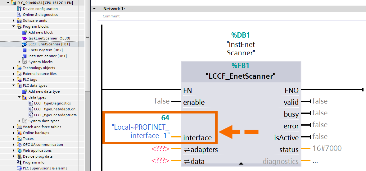
Choose the interface you plan to use and assign it as the parameter for the block.
The Scanner requires specific details to understand which Adapters fall within its range. This data includes Adapter addressing, the intervals at which Inputs and Outputs are updated, and the amount of data to transfer.
No graphical method is available in the TIA Portal for configuring inputs and outputs of the EtherNet/IP. Configuration for the 'Ethernet IP Scanner' function block is provided through an Adapter descriptions array. A global DB is the optimal place to keep descriptions.
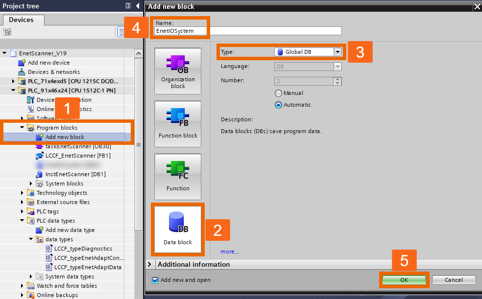
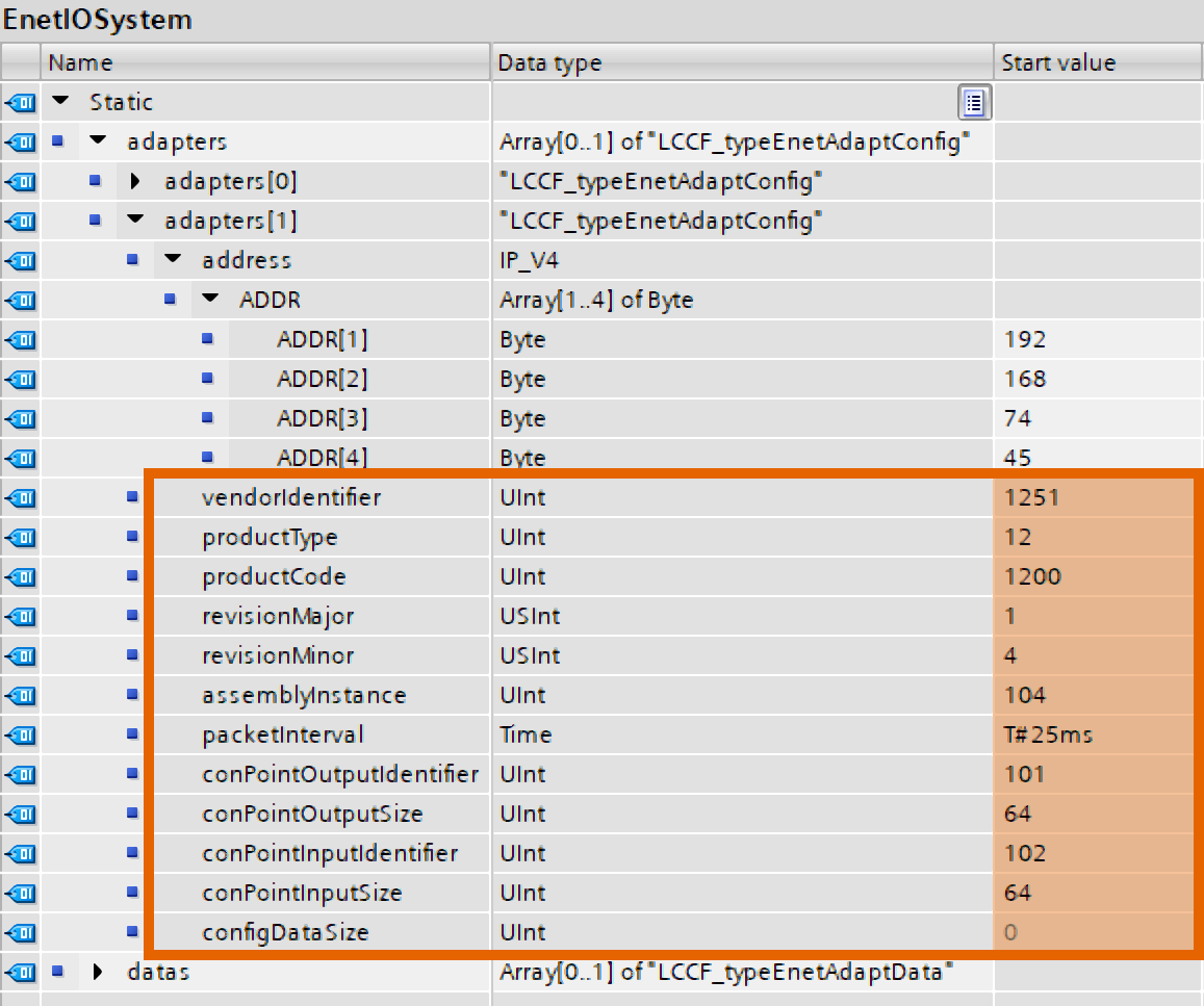
The 'Ethernet IP Adapter Configuration' type array within the created global data block includes all the crucial information for the 'Ethernet IP Scanner' function block to work correctly.
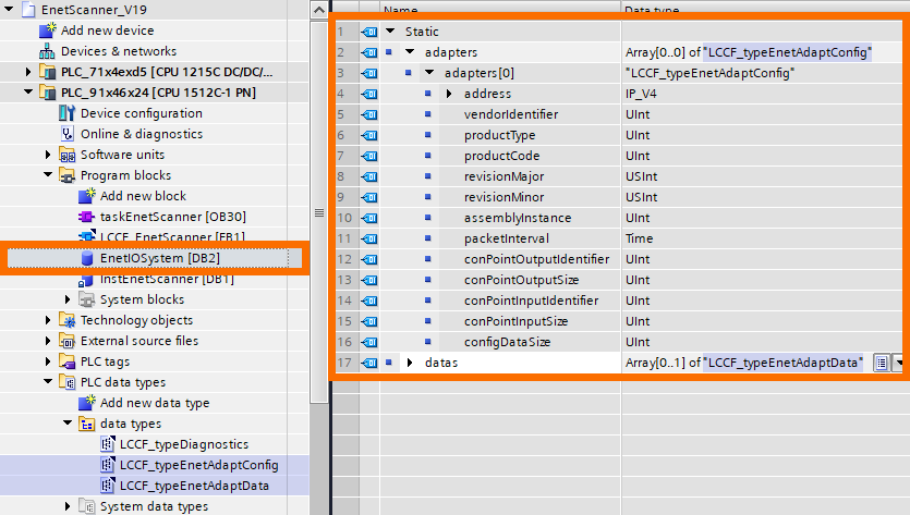
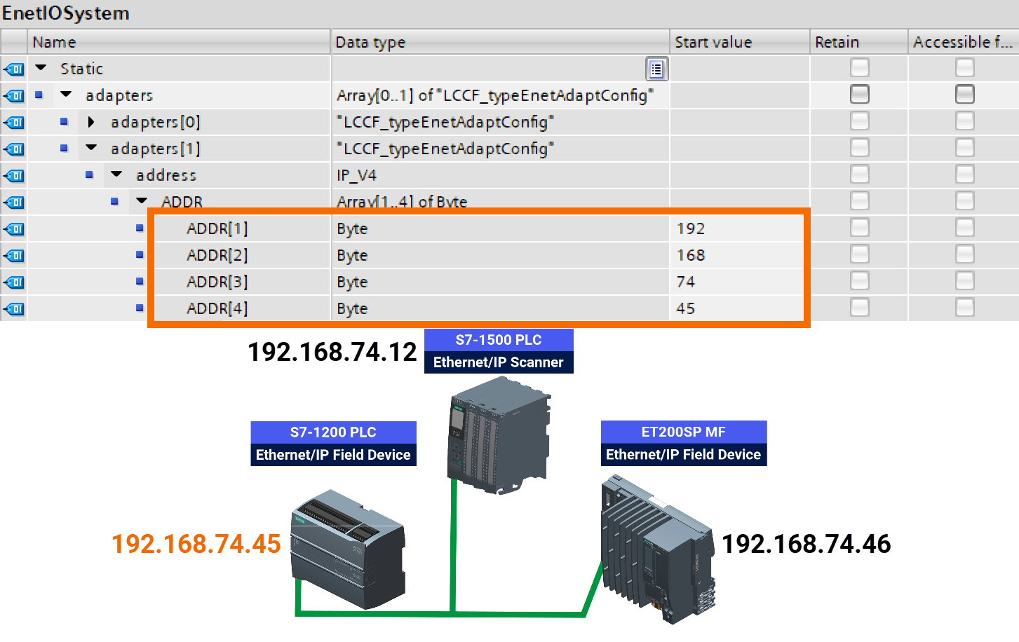
It holds essential addressing details. Among these is the IPv4 address where the Adapter is accessible. Your first configuration task involves setting up the ET200SP MF Adapter.

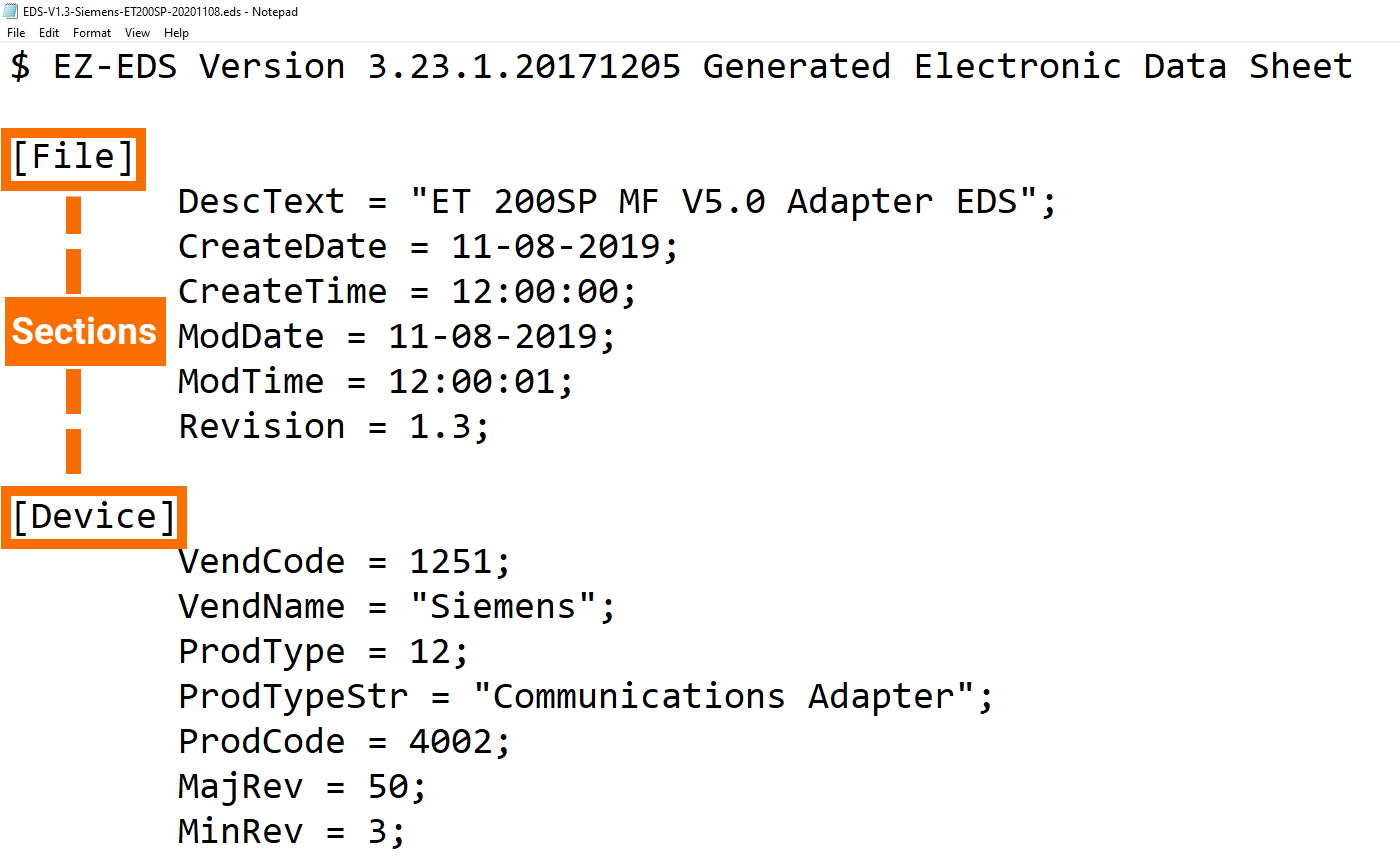
Extra information is essential and will be drawn from the provided Electronic Data Sheet (EDS). ODVA has standardized the EDS file format, designed in text form and readable by humans. Several groups of information, referred to as segments, are marked by square brackets and labeled with their respective names. In the following, you will learn which sections are needed for the 'Ethernet IP Scanner' function block and must be included in the Adapter description. The second Adapter will be handled using the same method.
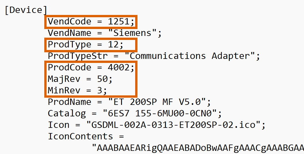
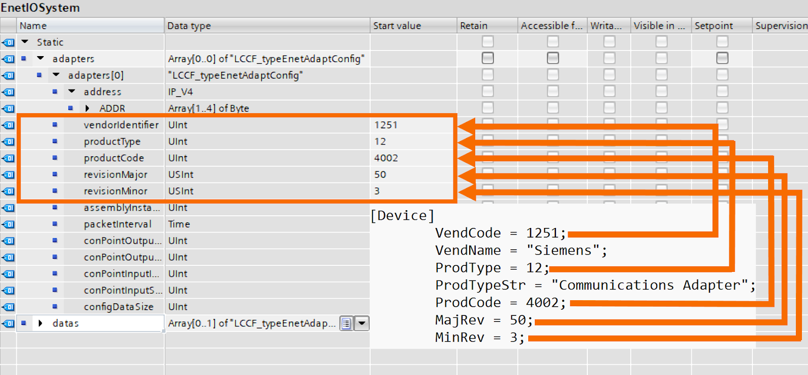
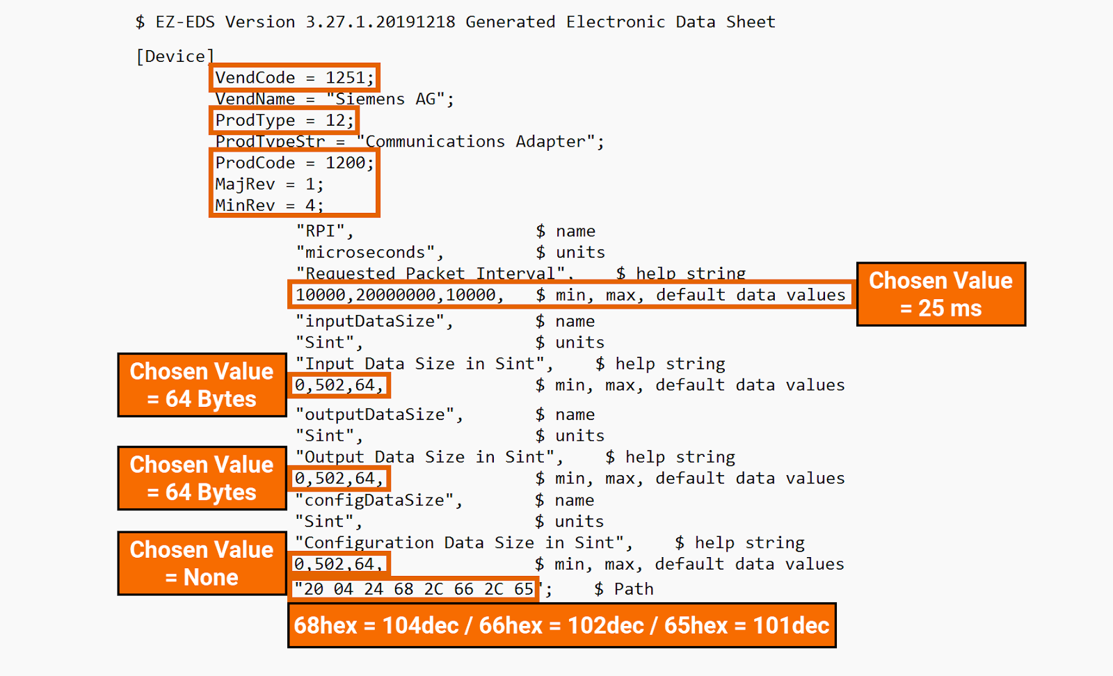
Details in the Device section help confirm the actual device matches the one set in the configuration. The device remains inactive if any mismatch is found before starting the operation. ODVA assigns the vendor identifier, labeled 'VendCode' in the EDS file, to identify the device manufacturer. The 'ProdType' in the EDS file represents a standardized numeric code identifying the device category. The 'ProdCode' number in the EDS file helps to uniquely recognize the device, its category, and its vendor ID. Ensuring compatibility involves checking both the major revision and minor revision numbers together.
Insert the specified data into the configuration within the global data block for this application example.
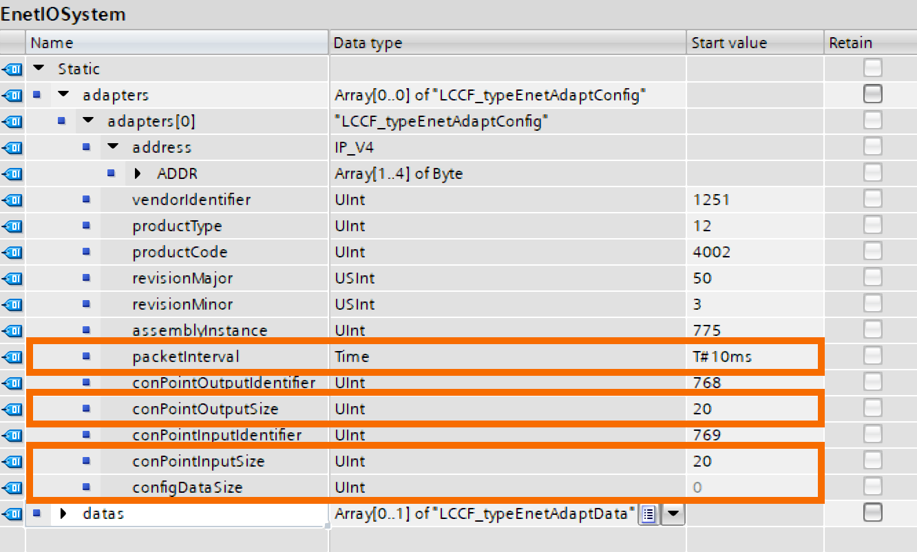
Other configuration parameters for the global data block, such as update intervals and input/output sizes, are in the 'Params' section of the EDS file. The update rate in microseconds is identified by the acronym RPI, standing for Requested Packet Interval. The range of update times for this device extends from 2ms (2.000µs) to 20s (20.000.000µs), and it defaults to 10ms (10.000µs). The EDS file also includes a vital parameter of the output data size in bytes. Valid sizes are between 0 and 246 Bytes, while the default value is the highest size available.

Scroll down to the 'Params' section to gather additional details such as input and configuration data sizes. The allowable range for input data size is from 0 to 500 Bytes. Since the configuration might not be present, the minimum size for the configuration data is not specified. Its maximum limit is 1 Byte.

Input the selected values into the designated fields within the global data block's Adapter description.
You must set up three crucial settings (assembly IDs) before enabling communication between the 'Ethernet IP Scanner' function block and the ET200SP. This information is presented mysteriously within the EDS file's 'Connection Manager' section.
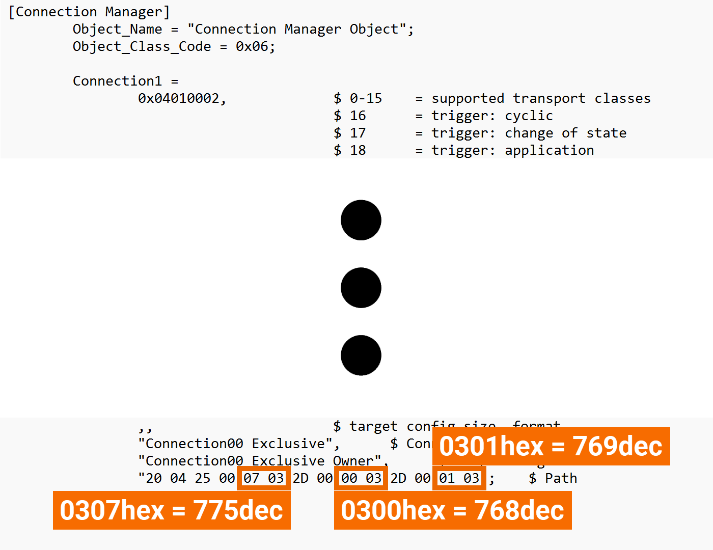
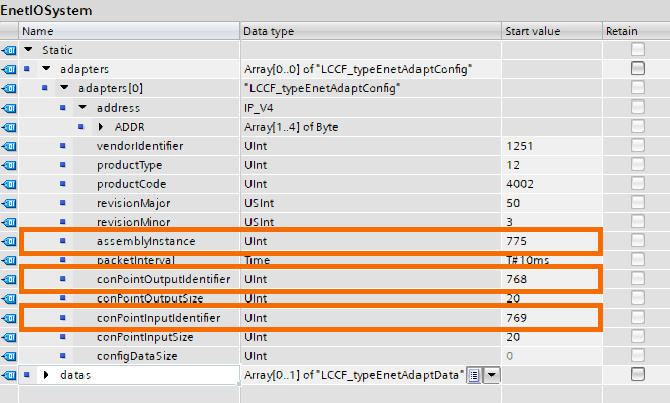
These assembly IDs are ready to be loaded into the global data block of the Adapter.
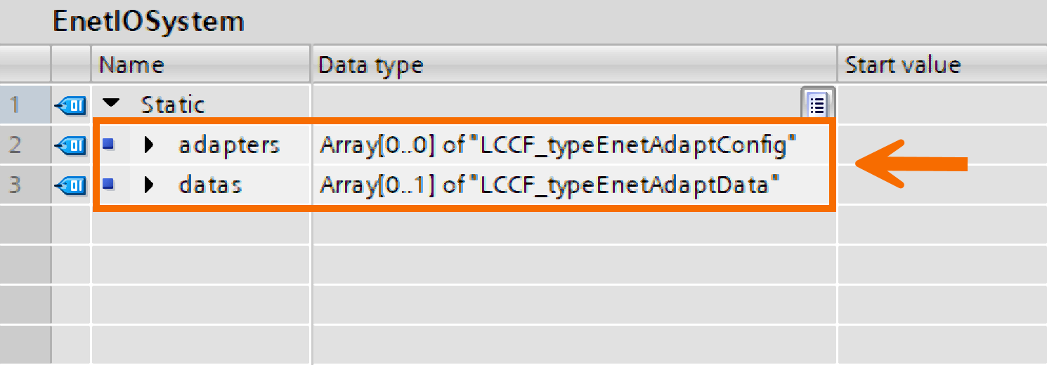
Verify that your global data block holds a minimum of two variables. Stored within the 'Adapters' variable is the freshly created ET200SP description. Data zones for Adapter exchange are kept in the 'Datas' variable.
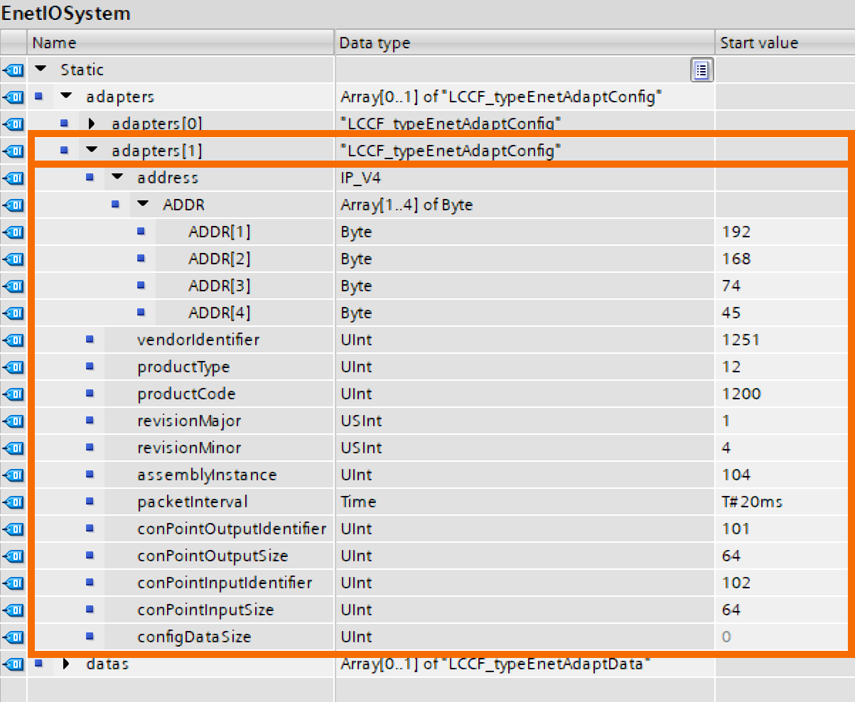
Expand the 'Adapters' variable to fit two units. Verify your input.

You will get a separate record for the second Adapter.
Fill in the second Adapter's IP address designated for the S7-1200 PLC.
Use a text editor like Notepad to open the second Adapter's EDS file and record the vital data from the different segments.
Insert the recorded details into the global data block.
Designate the variables to their matching parameters in the 'Ethernet IP Scanner' function block. The 'Ethernet IP Scanner' function block has been adjusted to include only the fundamental parameters.
Transfer the compiled program to the PLC, and if it is needed, change its status to run Mode. Once this process is complete, the PLC should operate and run the 'Ethernet IP Scanner' function block on a regular interrupt cycle (cyclic interrupt). A cyclic interrupt ensures the execution happens at specific intervals, keeping update rates consistent and jitter low.

Executing and Performing
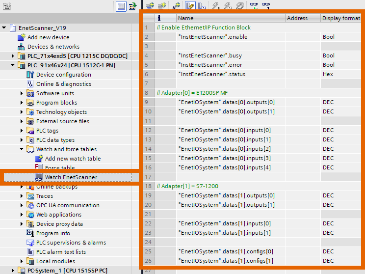
Generate a new watch table and configure it with the parameters you want to monitor in real-time mode.
Bring the watch table online for real-time value observation and modification.
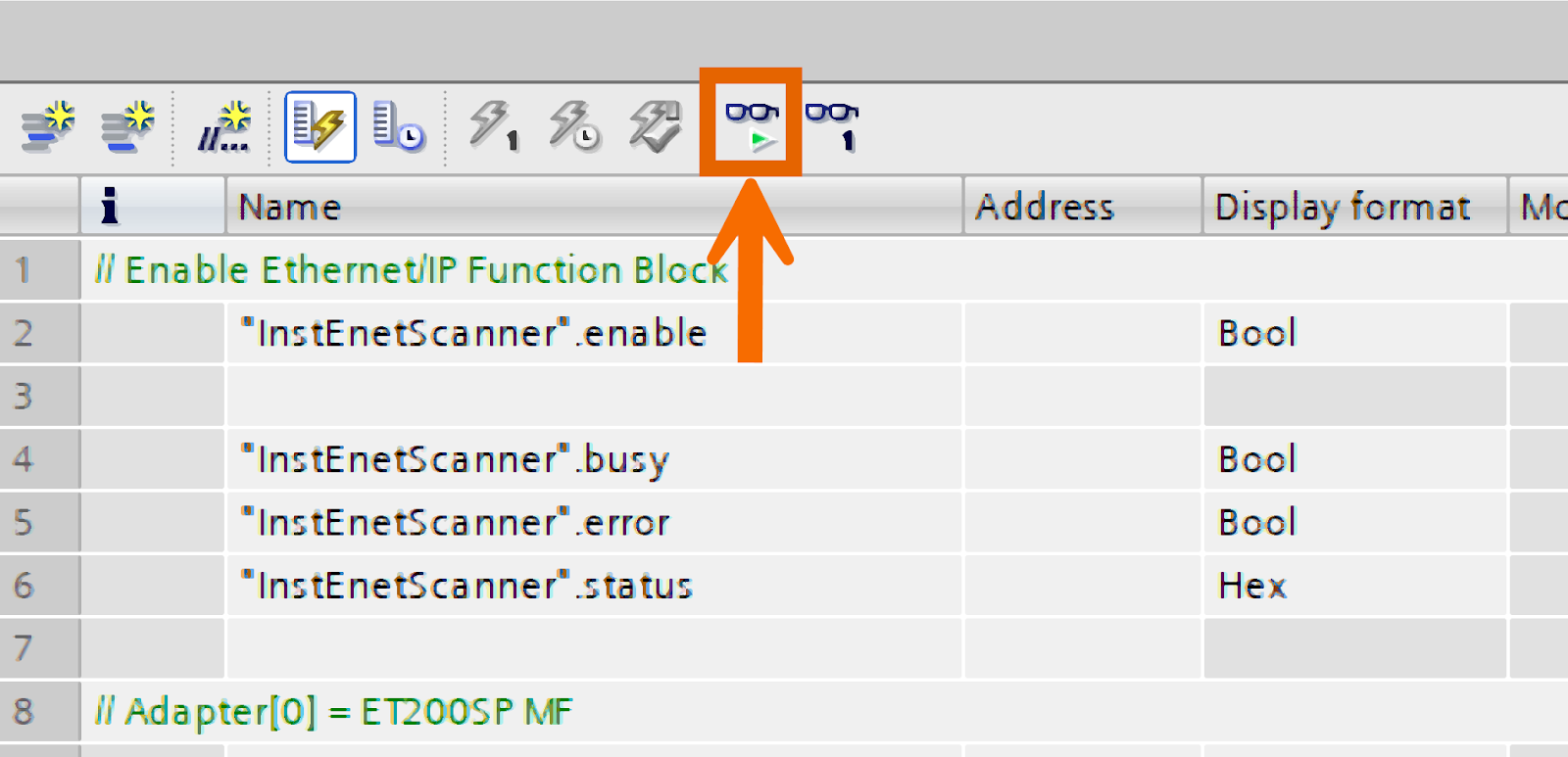
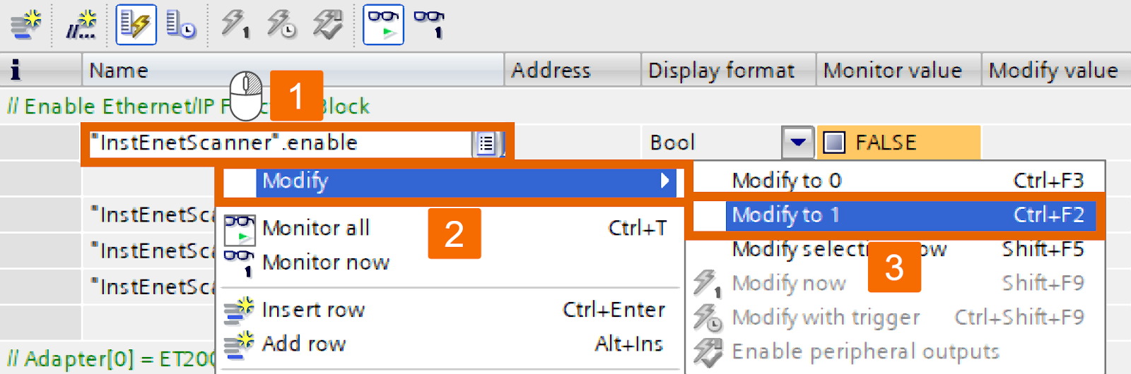
To activate the 'Enable' variable, set it to 'TRUE' by entering 'TRUE' or '1' in the 'Modify value' field or right-click to access the context menu and command from there.
Consequently, the 'Ethernet IP Scanner' function block initiates communication with the specified Adapters, beginning the data transfer process. The 'Ethernet IP Scanner' has a status of 16#7002, which points to it being busy, and the proper flags have been set accordingly.

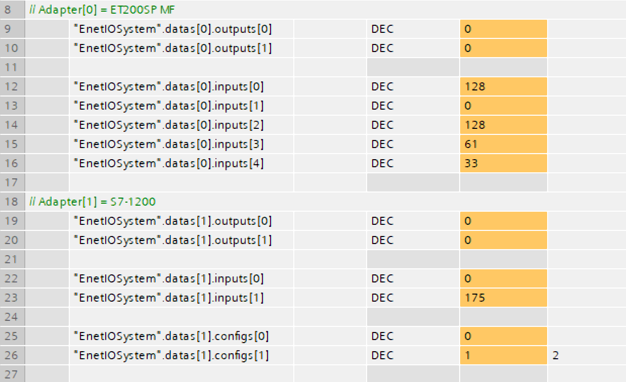
For each Adapter, update the output and supervise the incoming input data.
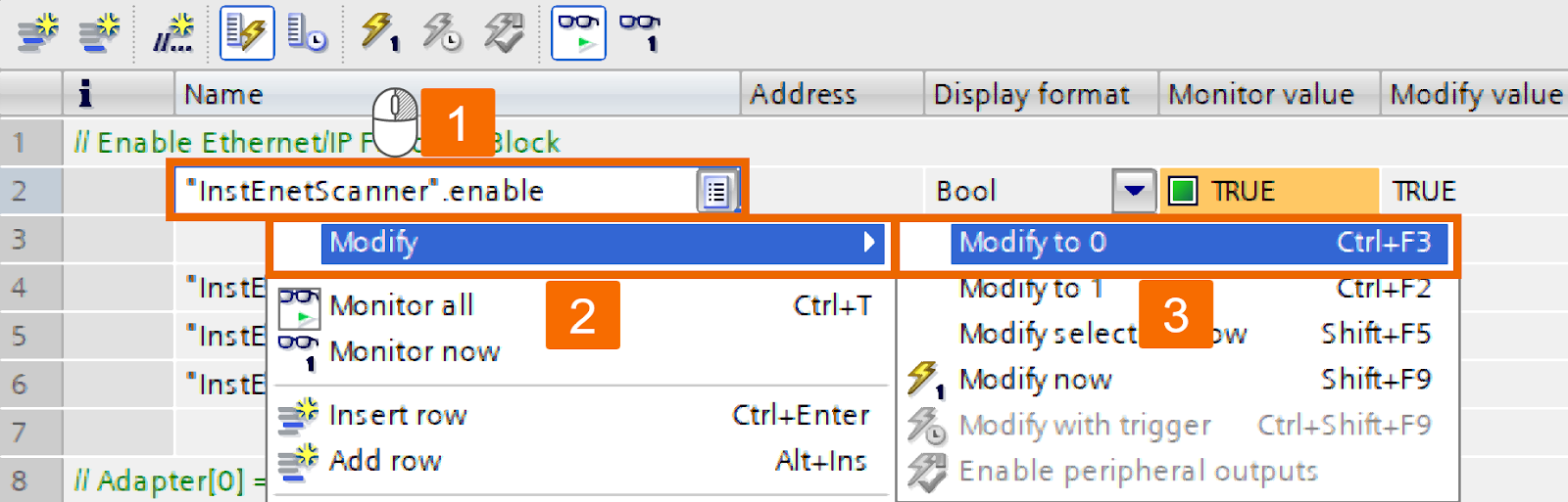
If you want to deactivate the 'Ethernet IP Scanner' function block, change the 'Enable' parameter to 'FALSE'. It leads to the freezing of input values and cessation of updates. The 'Ethernet IP Scanner' function block terminates connections to every configured Adapter.
Conclusion
In conclusion, you learned how to integrate EtherNet/IP field devices with Siemens PLCs, specifically the S7-1200 and S7-1500 series. This tutorial guided you through the setup process, including configuring the 'Ethernet IP Scanner' function block and managing Adapter descriptions using the Electronic Data Sheet (EDS) format. You also learned how to adjust critical parameters such as assembly IDs, update intervals, and data sizes to ensure smooth communication between the Scanner and Adapters. Finally, you gained insights into monitoring and managing the real-time communication process and how to manage the activation and deactivation of the 'Ethernet IP Scanner' function block to maintain operational efficiency.
