Introduction to SCL Programming in Siemens TIA Portal
Introduction
With the Industrial automation and IT worlds converging, IT specialists and Automation Engineers are pushed to develop new skills, in order to stay relevant in the industry.
IT engineers are entering the programming area and starting to write PLC programs using programming languages such as Python and C++, whereas Automation Engineers are learning to deal with SQL databases and being able to write PLC programs using high-level programming languages such as Structured Control Language (SCL).
In this tutorial, you learn about the SCL PLC programming language and how to get started with it in Siemens TIA Portal.
Prerequisites
In this tutorial, we use Siemens TIA Portal software version 16. However, you can use other versions to follow along. This tutorial is meant for people with practical experience with Siemens S7 CPUs such as S7-1200 and S7-1500 CPUs and those familiar with the fundamentals of Ladder Logic PLC programming language.
Still, if you are a beginner in PLC programming, you can follow this tutorial. Having the mentioned skills will speed up your learning process for SCL programming.
Siemens PLC Programming Languages
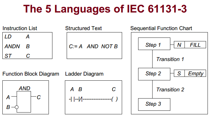
PLC programmers are acquainted with the standard that standardized programming languages for programmable logic controllers or PLCs. Five PLC programming languages are identified in DIN EN-61131-3 (or IEC 61131-3) standard:
- Ladder Diagram
- Function Block Diagram
- Sequential Function Chart
- Instruction List, and
- Structured Text
It’s important to mention that Structured Text (ST) is known as Structured Control Language (SCL) in Siemens software.
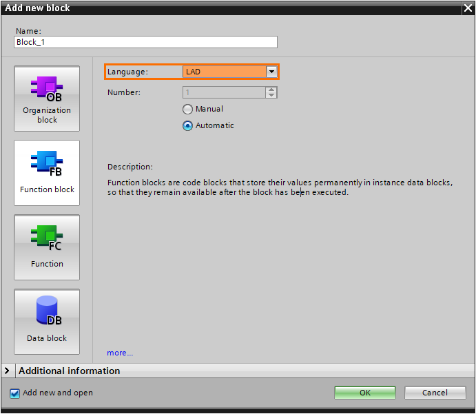
If you have ever programmed Siemens PLCs, you will know that when we create programming blocks, the Ladder Diagram is typically the default language and is generally acceptable for the new programming block.
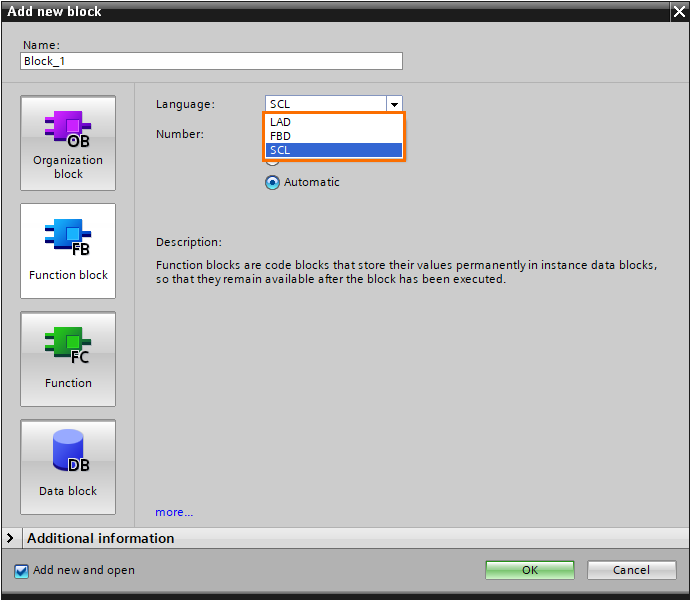
Three standard PLC programming languages are included in the majority of Siemens CPU types, which are Ladder Diagram (LD), Function Block Diagram (FBD), and Structured Control Language (SCL).
But what about Sequential Function Chart and Instruction List? Some Siemens CPUs also support these languages to provide total compliance with the IEC 61131-3 standard.

SCL Definition
SCL is short for Structured Control Language and is built on PASCAL and used for advanced programming. We use letters of SCL to define this programming language. We understand it is Structured Language from S and L letters, and from the letter C, we figure out Control. So, SCL is a structured language utilized to execute control instructions in Siemens PLCs.
Other forms of structured text languages may go by different names and be used by other PLC manufacturers. For example, Rockwell and Omron call this language the Structured Text in their PLC programming software.
Structured Control Language VS Ladder Diagram
If you have programmed Ladder Diagram before for Siemens PLCs, you know that its instructions are displayed graphically like counters, math functions, and shifts, to name a few.
So, a diagrammatic technique of presenting the logic’s flow, details, and connections to external I/O points is called a Ladder. In other words, a Ladder is designed to express a sequence of logic that the PLC should follow according to your programming instructions.
The same goal is achieved using SCL, but it employs a text-based language to carry out the same reasoning.
For instance, we can use a SUB block to subtract two variables from each other in the Ladder Diagram. But in the SCL, that subtraction can be represented using an equation that appears to be more typical.

Creating SCL Programming Block
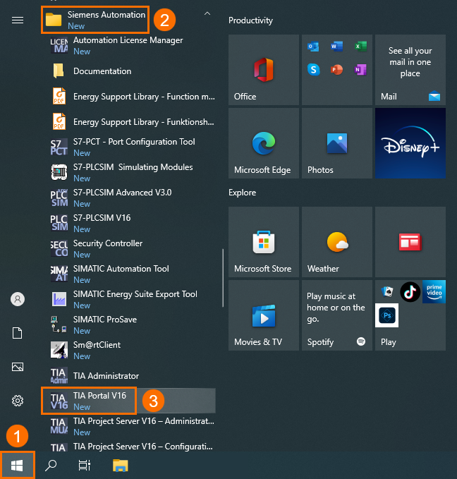
Let's begin creating an SCL program right away! We must first launch the Siemens TIA Portal. To do this, double-click over the TIA Portal icon on the desktop or press the Windows button on the bottom left side of the screen, scroll down through apps until you find and expand the Siemens Automation folder, and then click on the TIA Portal icon to open it.
Press the Create new project item, give our project the name SCL Programming and then hit the Create button.

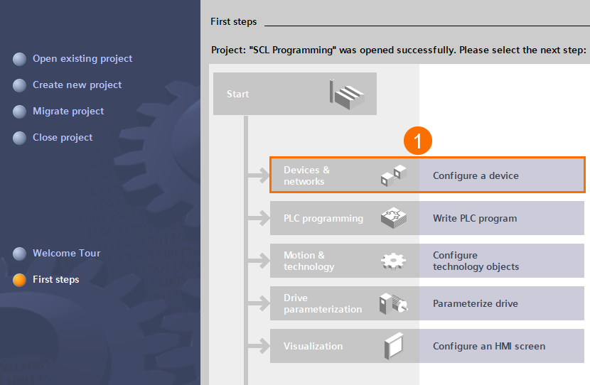
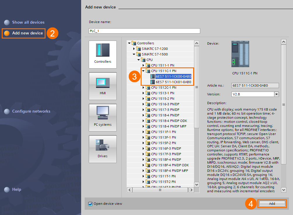
Once the project is built, we will add an S7-1500 CPU to create an SCL programming block. First, left-click over the Configure a device tab, select Add new device item, expand and go through the SIMATIC S7-1500 folder until you find and choose the CPU 1511C-1 PN, and then hit the Add button. One of the Siemens S7-1500 PLC Starter Kits uses this CPU and is popular among buyers.
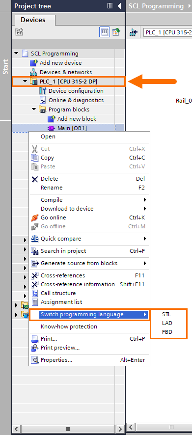
When the Project View is opened, right-click over the Main OB under the PLC_1 folder in the Project tree, select the Switch programming language item, and then a pop-up menu is displayed. We see that programming languages supported by this PLC model are Function Block Diagram and Ladder Diagram.
The STL (or Statement List) option is grayed out. All CPUs in S7-1200 and S7-1500 series have this trait. It’s worth mentioning that the STL programming language fulfills the Instruction List (IL) language defined in IEC 61131-3 standard.

If you have selected S7-300 or S7-400 CPUs for the PLC configuration, the STL programming language option is available for you to choose for programming their Main OBs.
To build the SCL program, double-click on the Add new block item under the Programs block folder in the left pane of the screen. When the Add new block window opens, select the Function tab and give the new block the name SCL Application.
Expand the Language drop-down menu and select the SCL. Leave the numbering method as Automatic since we want the possible new free block to be assigned automatically and to avoid occurring numbering conflicts during the compilation procedure.


Once the SCL block is created, it appears under the Program block folder in the Project tree.
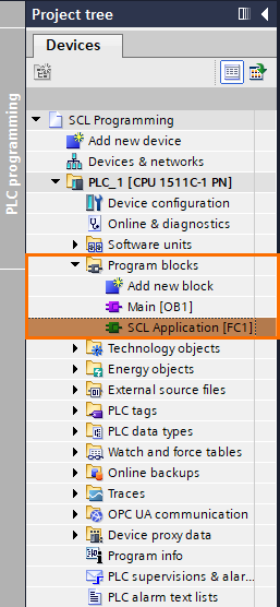
Double-click over the SCL Application block to open the SCL programming window, which is currently blank.
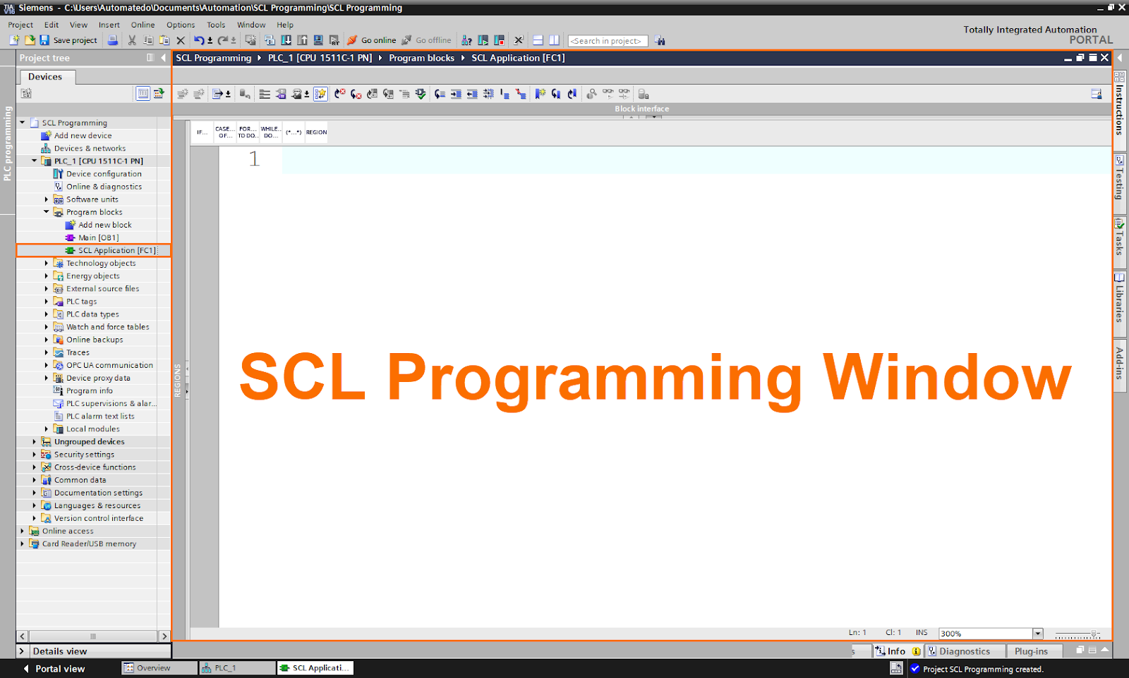
SCL Programming Window Overview
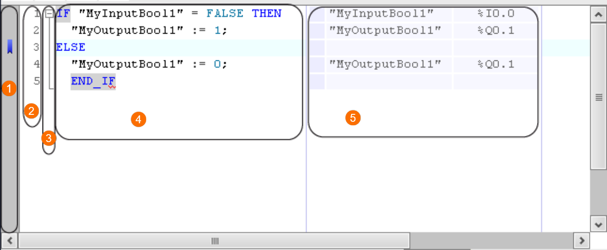
You can input the SCL program in the programming window, which serves as your workspace. Let us explore different sections that make up the SCL programming window:
- Sidebar: It offers the ability to specify breakpoints and bookmarks.
- Line Numbers: The program code is presented with the line numbers to the left of it.
- Outline View: It emphasizes code portions that are connected.
- Code Area: The SCL program is written, developed, edited, and modified in the code section.
- Display of the absolute operands: This table demonstrates the mapping of symbolic operands to absolute addresses.
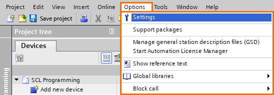
SCL Programming Window Customization
The TIA Portal gives you the power so you can customize how the programming window and program code look. To do so, select the Settings option from the Options menu in the top toolbar.
Once the Settings window is visible in the workspace, expand the General item and select the Script/text editors. As you can see, in the first two sections of this window, you can set the font, font size, and font colors.
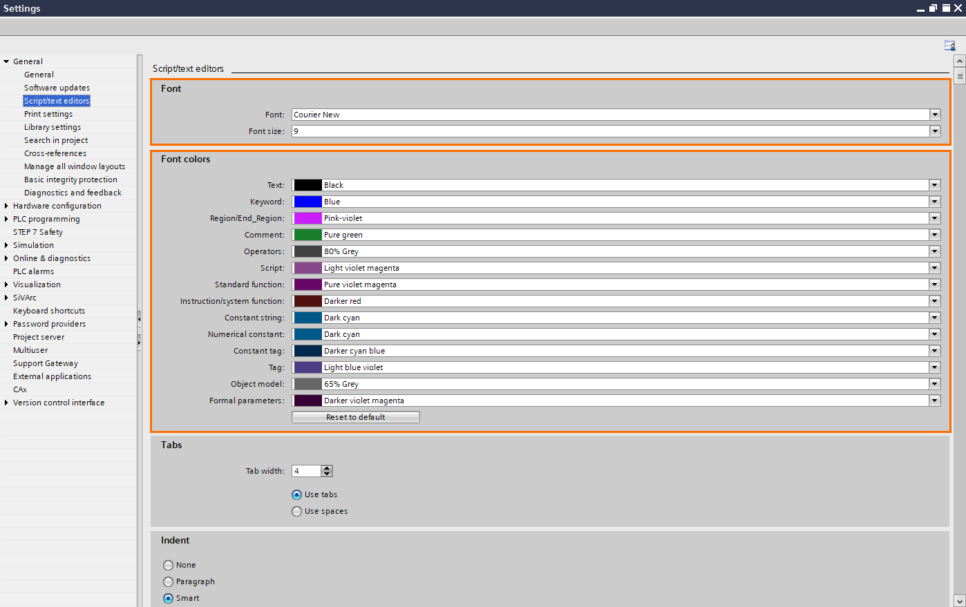
Based on syntax, lines are indented to give you a better picture of the program. You can use tab spacing to define the depth of indentation.

So, if you scroll down within the Script/text editors window, you can set the tab spacing. Also, you can choose the Indent among one of the three existing options: None, Paragraph, and Smart.

Additionally, you can show or hide the line numbers to the left of the program code. To do so, you can check or uncheck the Show line numbers box accordingly.

Conclusion
By reading this tutorial, you are now able to answer the following question:
- Why is it vital to learn SCL programming?
- Does the SCL language supported by the majority of Siemens PLCs?
- What is the SCL definition?
- What is SCL stands for?
- What do the other PLC manufacturers call SCL in their programming software?
- What is the difference between Structured Control Language and Ladder Diagram?
- How do we create an SCL programming block in the Siemens TIA Portal software?
- How can we customize the SCL programming window?
The skills you gain in SCL programming will allow you to build and test efficient, reliable PLC logic for various applications and tasks.


