The Complete Guide to Industrial Level Sensors
Introduction
Level measurement is one of the most common parameters measured in process industries. Level sensors use one of several principles to detect the level of liquid in a container and convert the measurement to electrical signals or a mechanical movement for local indication. Some of the types covered in this article include visual detection, capacitance, conductivity and ultrasonic type level sensors.
Some of the applications of level measurement include food processing, water treatment, oil refineries, and chemical manufacturing. Accurate measurement of level helps ensure the quality of product such as in the case of food manufacturing; health and safety of consumers in case of water treatment plants; and overall reduces operating costs by using the right amount of raw materials.
Some of the more commonly used types of industrial level sensors are float switches, ultrasonic, pressure, and capacitance type sensors. The nature of the fluid, the material of tanks, and the desired accuracy determine the type of level sensor to be used.
This article will cover level monitoring - operating principles of different types of level sensors, considerations such as costs, suitability, accuracy, and challenges associated with different level measurement methods. We will discuss the different types of electrical signals supported by different sensors and how to interface them with PLCs.
An understanding of the concepts of head pressure, current, and voltage connections will make it easier to follow this article.
Types of Level Sensors
Even though sensors have advanced tremendously in the past few decades, purely mechanical sensors still have a place in the industries. In this section, we will cover both mechanical and electronic level sensors.
Mechanical Sensors
Mechanical sensors use purely mechanical ways of sensing and indication without any electronic signal or signal manipulation. This section covers a couple of basic mechanical sensors. The disadvantage with these types of sensors is that there is only a local indication with no data sent to the control room.
Float
This is the most basic way of measuring the level of liquids. In this method there are no electronics involved, construction is very simple with a floating component(also referred to as a float) attached to a string and an indicator that is suspended on the outside of the tank. As the liquid level changes the float moves up and down - this causes the indicator outside the tank to also move up and down along a graduated bar. By simply looking at the indicator outside the tank one can find out the tank level. Some water storage tanks in water treatment plants still employ these sensors for their simplicity in design and low cost.

The above picture shows how the float is connected to the indicator/counterweight. As the float moves up and down the indicator also moves to show the correct level.
Glass Tubes
This type of measurement uses a very rudimentary principle to measure the tank level and display. A transparent glass tube is connected to the bottom of the tank with graduations on the tube. When both the tube and the tank are exposed to the same pressure the level of liquid in the tube is the same as in the tank. This is because in a homogenous liquid the hydrostatic pressure is the same according to Stevin’s law.
This method is only good when a local readout is sufficient, it has no electronics involved. It doesn’t have any moving parts so maintenance is easy. Another disadvantage is that if the process liquid is not clean it can leave a residue inside the tube rendering it useless over time.
.svg)
The picture above shows a tank connected to a sight tube with gradations and isolation valves for maintenance
Electronic Sensors
Electronic level sensors need electronic components for converting mechanical movement or sound waves into electrical signals. These signals are then sent to the control room to display data and control pumps and other equipment. The downsides of these types of sensors are costs and complexity of maintaining the sensors. However the advantages of accuracy, speed and availability of data in a remote location are compelling reasons to prefer them in most applications.
Float Switch Sensor
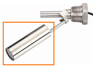
In this type of sensor the float activates a switch when the level rises above or falls below a preset value. When the switch is activated it can send a voltage signal to a PLC. This can be used to control a pump or as an alarm. These sensors are very widely used as they are simple to understand and operate. There aren’t many moving parts and the accuracy is high. They are very cost-effective making them a preferred choice in industrial as well as residential applications.
One disadvantage of float switch sensors or any other contact type sensor is that they cannot be used to measure the level of corrosive liquids unless special measures are taken. To overcome this challenge ultrasonic sensors are a great choice.
Ultrasonic Sensors
Ultrasonic sensors have the advantage of not having any moving parts and of being non-contact type. The device emits a sound at a very high frequency - ultrasonic frequency - and waits for the sound waves to bounce back from the liquid surface. These reflected sound waves are detected by the sensor. The time taken by the sound wave to travel to the liquid surface and back to the sensor is used to calculate the liquid level.
For accurate results, it is critical to follow mounting instructions from the manufacturer.
The sound beam emitted by the device is in the shape of a cone. If the tank diameter is too small, it affects the readings. Sound tubes can be used to make the sound beam narrow to prevent the sound beam from hitting the tank walls and prevent inaccurate readings. Ultrasonic sensors are usually costly.
There are continuous measurement types as well as fixed level measurement types. Measurement of ultrapure water(<= 0 ppm of total dissolved solids) level is an excellent example of an application of ultrasonic sensors.
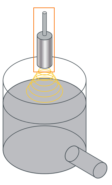
The picture above shows a tank with a liquid level being measured by an ultrasonic sensor. The sensor is highlighted by an orange box. The yellow concentric circles represent the conical sound beam.
Non-Contact Capacitance Sensors
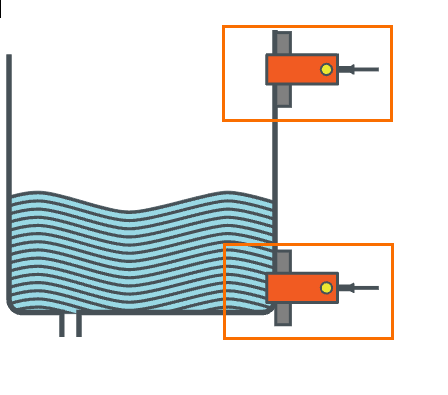
Non-contact capacitance sensors are an excellent choice when there are concerns of corrosion or contamination. This type of sensor is mounted along with the tank on the outside. The material of the tank and the liquid are important considerations - for example, the sensor can differentiate between the presence and absence of water in a glass/plastic tank. But metallic tanks can affect the readings. These types of sensors are usually used as level switches to measure a high or low level.
Wiring and Connecting a Level Sensor to PLCs
Analog level sensors can either send a 4-20 mA signal or a 1-5 V DC signal. These signals are hooked up to a PLC input analog module to convert the raw reading into a human-readable value. The level measurement is used for displaying the level reading or for a control action such as operating valves or turning on/off pumps.
4-20 mA current loops are some of the most common signals in industrial applications. 4 mA corresponds to the lowest value of measurement and 20 mA corresponds to the highest value. The reason 4 mA is used instead of a 0 mA signal is to differentiate between a reading of the lowest value and a broken wire connection. Most PLCs have a built-in 4-20 mA connection or have expansion modules that can measure 4-20 mA signals.
1-5 V DC signals are also some of the oldest and widely adopted, just like 4-20 mA signals. This voltage signal can then be wired to a PLC analog input module and the PLC can be programmed to convert the voltage into a level measurement.
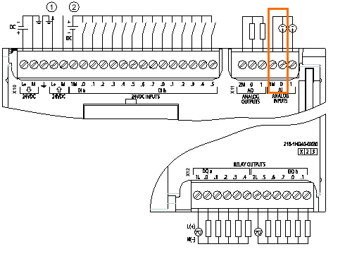
The above picture shows a 1215c AC/DC/Rly Siemens PLC module with two analog inputs. The highlighted area shows how an analog level sensor can be wired to this PLC module. The circle with ”+” and ”-” represents an analog level sensor.

The picture above shows a Siemens code snippet for measuring 4-20 mA or a 1-5 VDC input signal. The analog input is scaled to represent an engineering value of 0.0-10.0 level in chosen units. When the scaled level reaches 1.5 or lower a pump is turned on. Upon reaching a preset level the digital level sensors send a voltage signal that is detected by the PLC and used for control action such as turning on/off a pump.
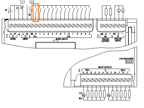
This picture above shows a Siemens PLC 1215c AC/DC/Rly CPU. The highlighted area in orange shows a digital switch connected to the input of the PLC.

The Siemens code snippet above shows how a digital level sensor can be used to turn off a pump when the tank reaches a high level.
In addition to analog modules, PLCs also come with expansion modules for protocols such as RS485, PROFIBUS, and IOLink that are commonly supported by various instruments.
Conclusion
In this tutorial, we have discussed what level sensors are, why they are one of the critical components of automation in process industries, and some of the most commonly used types of level sensors. We have also briefly covered analog & digital wiring connections to PLCs and sample Siemens code snippets to demonstrate how the signals can be scaled and used to control the level in a tank.


