PLC Programming Example Project - Batching Tank Ladder Logic PLC and HMI Tutorial
Introduction to Batch Processing
Generally speaking, there are two types of processes in manufacturing: discrete and analog. A discrete process is a manufacturing methodology that will produce separate widgets. In other words, a production line may output one item, two items, three items, etc. An analog production process is where the plant will create a quantity of product that is quantifiable by weight. Examples include the production of beverages, sauces, raw ingredients, etc. Although it is possible to design a flow that will continuously output the product, such production is often managed in batches. It is important to note that although batches are considered to be analog or continuous flow, most of them end up being packaged for consumption which converts them into a discrete manufacturing process.
A batch is a certain volume of product to be produced in a single run. Let us look at the simplest example of a batch:
A mixing tank has two in-feed pipes coming from a source of water and sweet syrup respectively. An operator is able to open the flow of water or sweet syrup into the mixing tank.
In this case, a batch would be the action of creating a specific mixture of the two inputs in the mixing tank. For example, a batch can be defined as 5000 pounds of water and 200 pounds of sweet syrup. A different batch may contain 4500 pounds of water and 700 pounds of syrup. Note that although the total weight is the same in both cases, it may vary between batches.
Project Solution, HMI and PLC Files Download
SolisPlC GitHub PLC and HMI Files
Why is batching important?
As we had mentioned above, it is possible to create a process in which the end product would be continuously delivered as an output. Why is there a need for batching at all?
- Batching helps with quality control. As a batch is finalized, QC procedures are applied and the batch is thoroughly tested. Any deviation from the specification sheet allows the plant to discard the batch, eliminate the issues that caused the deviations and proceed with a new batch. This reduces the amount of waste that may be created.
- Batching allows the factory to control production runs based on demand. In other words, customers will typically request a limited quantity of a certain product. Once the run is finished, the production team will sanitize the equipment, enter new batch parameters and start a new run.
PLC Programming Example - Batch Control
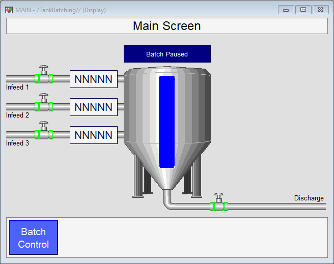
To better understand the batch production process, let us take a look at a simple system. As mentioned above, a mixing tank that receives a set of ingredients is that most basic example of a batch process. In this section, we will take a look at a PLC programming example that controls a tank which is filled with three ingredients. We’ve also implemented a basic HMI design that will aid in the control as well as visualization of the process.
Step 1 - Inputs, Outputs and PLC Program Layout
Let’s start by understanding the system. Our PLC unit controls a set of input valves, a discharge valve, receives information about the quantity of liquid we’ve sent to the tank (via a simulated flowmeter), displays basic information about the system and allows the operator to send ingredients into the tank. Here’s a basic breakdown of this system:
- Input Valve 1 | [Digital Output] Ingredient 1 Infeed
- Input Valve 2 | [Digital Output] Ingredient 2 Infeed
- Input Valve 3 | [Digital Output] Ingredient 3 Infeed
- Flow Meter 1 | [Analog Input] Ingredient 1 Flow
- Flow Meter 2 | [Analog Input] Ingredient 2 Flow
- Flow Meter 3 | [Analog Input] Ingredient 2 Flow
- Output Valve 4 | [Digital Output] Batch Discharge
Note: the list of items above in non-exhaustive. In a typical mixing tank application, the PLC programmer should expect to have a level sensor, limit switches, position indicators on each valve, metal detectors, reject stations, load cells, and more. However, the purpose of this PLC Programming example is to illustrate the purpose of batching. Therefore, we’ve omitted a lot of external components that would cloud this tutorial.

Step 2 - HMI Controlled Batching
In a system with no batch control, the operator is required to open a single valve and monitor the flow until it reaches a certain setpoint. At that point, he would close the valve and proceed to the next ingredient. In a control system that has a batching feature, the operator will either set the quantity of each ingredient or simply select the recipe for the batch. The system would take care of the rest.
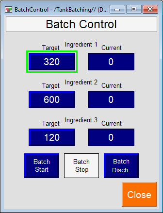
The HMI control screen displayed below is used to start, stop, discharge and set the targets for the batch. Notice that although the operator is able to adjust the targets at any time, the appropriate buttons are disabled in certain conditions. The user is only able to start the batch when the tank is empty,

Step 3 - Batching PLC Programming
We start building the foundations of the project. The start and stop functionalities are common to every PLC programming project; we’ve seen the exact same pattern for a motor starter. Similarly, when we start a batch discharge, we want our system to complete the process based on certain conditions before we stop.


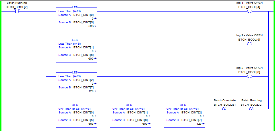
Once the batching has started, we need to track our ingredients against the targets set by the operator on the HMI. The logic is simple in this case; we open the valves while the quantity we’ve received is below the target and close the valves once we reach the target. The rung below illustrates how we achieve this in ladder logic. Additionally, the rung will set a “Batch Complete” bit when all the ingredients have reached their setpoint.

We need to monitor the state of the tank and know when it’s empty as well as when it is full. These conditions are used to fill the batch and to stop the tank discharging when it has been emptied. The rungs below accomplish these tasks.
In addition to the conditions of “Empty” and “Full”, the rungs are used to compute additional information. The “Tank Full” condition references the weight that was transferred by every ingredient. The “Tank Empty” condition is used to reset the flowmeter values for every ingredient.
The above is accomplished due to the fact that our system does not have a flowmeter at the discharge. Furthermore, once the ingredients are mixed into the batch, you’d have to measure a combined output as you could not specifically display how much of each ingredient you have discharged. Lastly, it’s typical in such systems to have a non-flow metered output to save on cost.


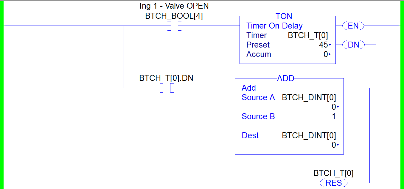
Our batching project is complete. However, we still need to test, simulate and validate the ladder logic we’ve created. By creating an additional routine, we can build ladder logic that will simulate the functionality of a flowmeter while the system is running.
The rung shown below will increment the flowmeter value after a set amount of time has elapsed. Note that the parameters of this rung can be easily adjusted in order to increase or decrease the rate at which this specific “flowmeter” will operate. The programmer may change the Preset variable of the TON instruction or the amount that will be added each time the timer is done.

Conclusion
Batching plays an important role in chemical, food, beverage and other types of manufacturing processes. Building a simple batching system is an excellent PLC Programming Project for anyone learning PLC and HMI programming. Not only are these systems used in real applications, they provide the programmer with multiple challenges that can be applied in many other applications and help the programmer learn new skills.
The project we’ve covered above illustrates a simple batching process that takes three ingredients, sends them into a mixing tank and discharges the mixture once the process is complete. The PLC and HMI Programs implemented provide a user interface for monitoring and controlling the batch at every stage of the process: Start, Stop, Discharge. You can also use the screen you've built here in your Manufacturing Execution Systems (MES).


