Siemens LOGO PLC Training | How to Get Started with Siemens LOGO Soft Comfort
Introduction Siemens LOGO PLC
Siemens LOGO PLC is a compact control system designed for small automation projects. It can be programmed using LOGO Soft Comfort. This software offers a graphical interface for creating and editing programs.
Generating a new circuit program is essential for creating customized control systems. Picking out and placing blocks within the program enables the user to design the logic functions for the system.
Shortcut menus for editing objects offer a more efficient way to apply changes to the program. Configuring blocks allows for program customization to meet specific system requirements.
Establishing connections between blocks is necessary for the program to function correctly. Understanding block connection tips can help to avoid errors and ensure smooth operation.
In general, mastering these skills is crucial for the efficient and effective programming of Siemens LOGO PLC.
Prerequisites
To be able to follow this tutorial, it is necessary to have the Siemens LOGO Soft Comfort software installed on your computer. While the tutorial specifically references version 8.3, other versions of LOGO Soft Comfort can also be employed.
Generating a New Circuit Program
Start by opening the Windows start menu. Scroll down until you find the Siemens LOGO Soft folder. Expand it and select the LOGO Soft Comfort software to open it.

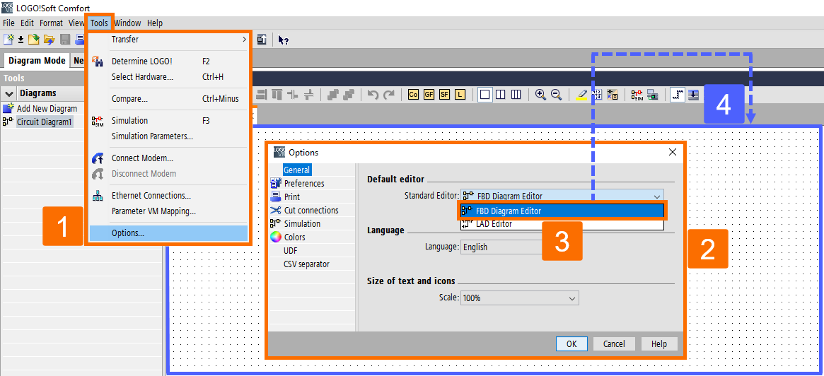
Click on the File menu and choose the New command to generate a new circuit program. Thus, you can open the Function Block Diagram, Ladder Diagram, or UDF Diagram editor. Or you can select the New button located in the standard toolbar.

By doing so, the software will launch the FBD Editor (or the default editor set in Tools/Options/Standard Editor). It enables you to generate the new circuit program in a new window within the programming interface.
Picking Out Blocks in Siemens LOGO Soft Comfort
The initial step in programming is to choose the appropriate blocks for your circuit program. Also, decide on the sequence you wish to insert the I/O and standard/SFB blocks. The constants and terminals, which comprise a set of I/O and constant signals, can be found under Co in the programming toolbar.

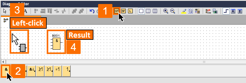
Located under GF, you can access the fundamental logic functions of Boolean algebra - standard digital logic blocks. It is solely accessible to the UDF and FBD Editors.

The special functions can be found under SF. You can also access the mentioned function groups using the function keys.

Placing Blocks in Siemens LOGO Soft Comfort
To access the desired block, click on the icon group that contains the block. Alternatively, you can press the corresponding function key. Upon selecting a function group, the programming interface will present all blocks associated with it. Click directly on the interface to add the selected function to your programming interface. Using the mouse, you can choose other blocks before placing them. It is not necessary to align the blocks immediately, as a precise alignment at this stage is meaningless. Until the blocks have been interconnected and comments have been added to the circuit program.
There are two options available to you besides the standard selection of blocks from the programming toolbar icons.
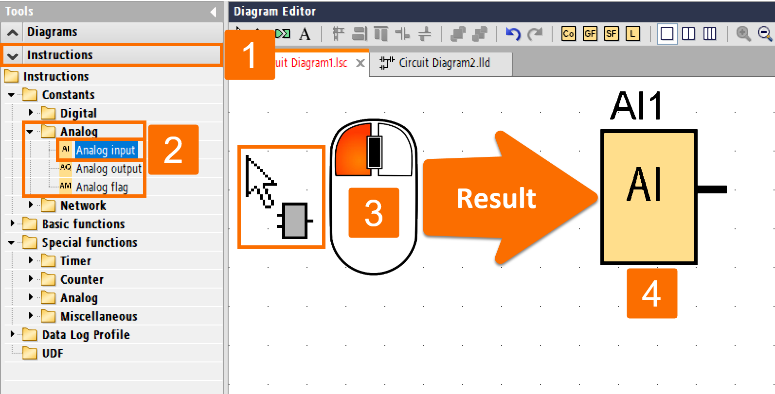
To use the first method, you can expand the catalog from the instruction tree and select the desired block. Then, left-click on the block insert position in your circuit program, and the block will be inserted at the correct place.
The advantage of this method is that you can easily switch between constants/terminals, SFBs, and basic functions. So, you don't need to click on corresponding icons in the programming toolbar.
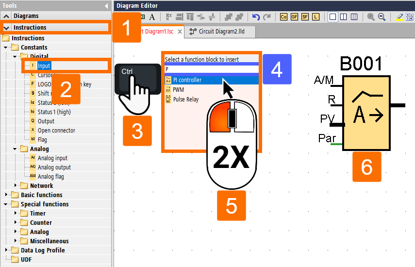
The second method involves opening the programming toolbar catalog and selecting any block by clicking on it. It's better to close the catalog and hide the programming toolbar if you're working on a massive program. Then, by holding down the Ctrl key and left-clicking on the block insert position, a mask with a block list will appear in your circuit program. You can quickly select the required block from this list by double-clicking on it. If you want to narrow the list, use the input field in the mask header. To do this, enter the initial letter of the required block to restrict the display to a list of blocks with this initial. It can save time and help you quickly find the relevant block without browsing the entire mask. Once you've selected the block, the software will insert it at the appropriate position in your circuit program. If you need to insert more instances of the same block, left-click on the relevant insert positions.
Shortcut Menus
Shortcut menus can be accessed by right-clicking on an object, which provides several editing options. The editing options available will vary depending on the type of object chosen. Objects include blocks, connecting lines, the programming interface, and toolbars.

Configuring Blocks in Siemens LOGO Soft Comfort
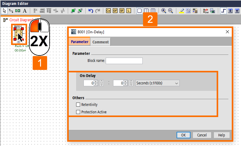
By double-clicking on a block, you can access the properties dialog box to configure the block properties. It includes the Comment tab alongside parameter tabs for special function blocks, some basic functions, and constants and connectors. Here is where you can input the values and settings for your blocks.
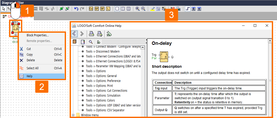
To get help on the selected object and its parameters, right-click over it within the programming interface. Then choose the "Help" item from the shortcut menu. It will display a relevant help topic associated with the object. It also provides additional guidance and information.
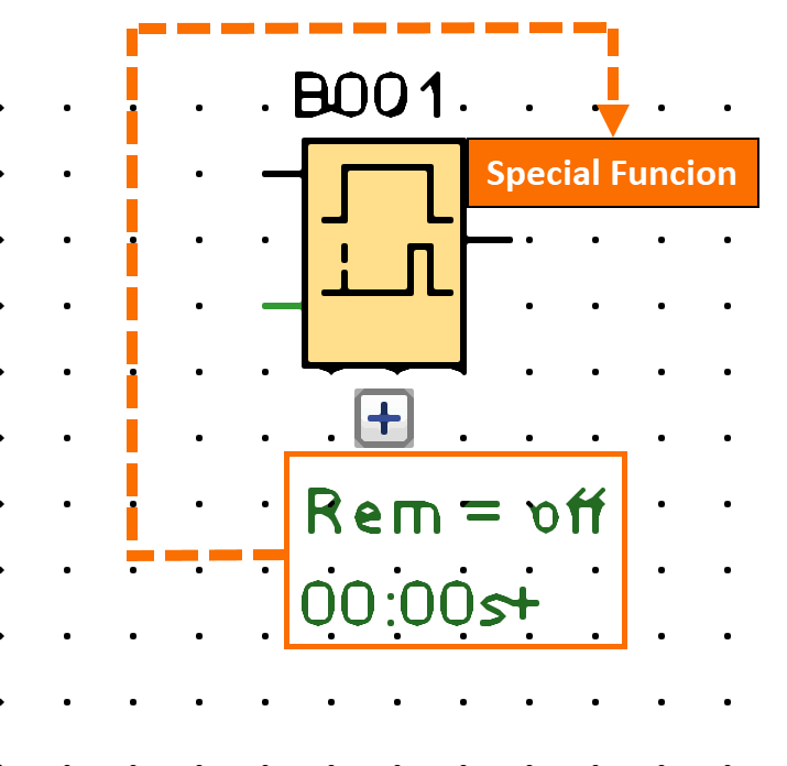
The green lettering beneath the block on the programming interface indicates that it is a special function.
Establishing Connections between Blocks
Interconnecting the blocks is essential to complete the circuit program. To do so, navigate to the programming toolbar and left-click the block connection icon.

How connecting two blocks can be accomplished? You can click on one block's connector and drag the mouse to a connector of another block. The software will then establish a connection between the two terminals.

Figure 6.2:
When using LOGO Soft Comfort, you can connect blocks in different ways. Once you right-click on the block's input or output, a shortcut menu will appear. From there, select the "Connect with…" option to view a list of all available blocks to connect with. Choose the desired target block, and the software will draw the connecting line automatically. It is helpful when connecting a source and target block over a longer distance on the programming interface is needed.
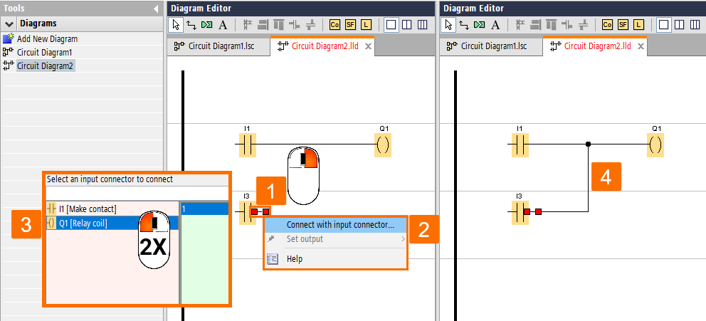
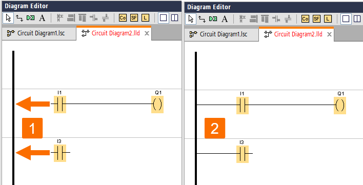
It is essential to ensure that the I/O is connected to the left-hand bus bar in the editor window when you work with the Ladder diagram editor.
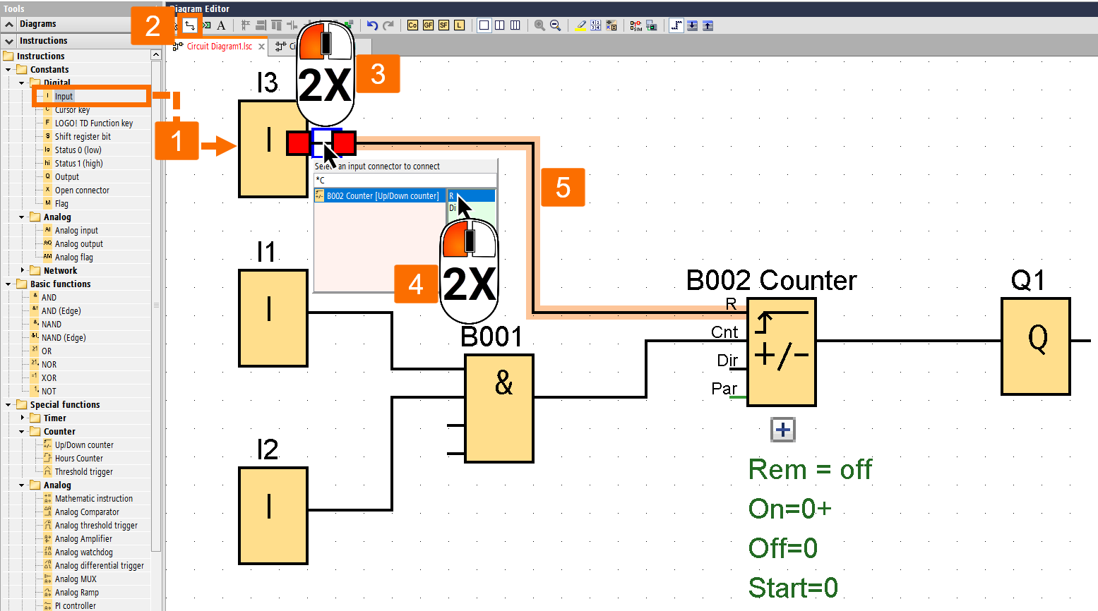
Aside from the standard approach of creating connections, an alternative method is available. Once you have placed the desired block into your circuit program, you can double-click on the input or output of a block to open a mask with a list of target blocks. There, you can quickly select the desired block by double-clicking on it. The mask header also includes an input field that you can use to narrow down the list of blocks by entering the initial letter of the required block. Also, you can use wildcards such as *. It can save time and help you find the relevant block more efficiently, especially when working with large circuit programs. The software will then automatically create the connection between the two blocks. Thus, this method provides a quick and easy way to generate connections in your circuit program.
Block Connection Tips
LOGO Soft Comfort will present a tooltip displaying the connection when you link an input to an output or vice versa. You can then snap the line onto the indicated input terminal by releasing the mouse button.

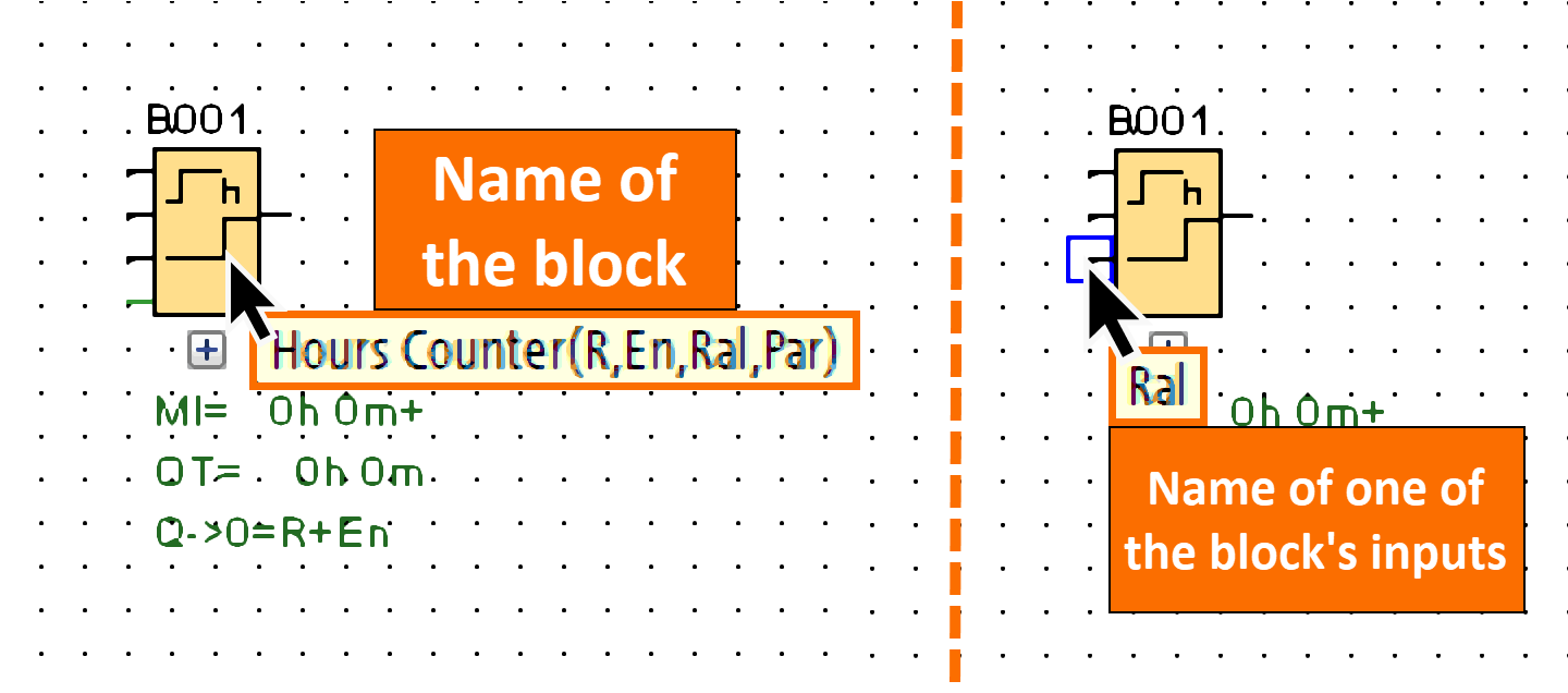
If you need extra help with circuit programming, you can rely on short information called tooltips provided by the software. If you hover over a block, you can view its name, while hovering over a block input will reveal the input's name.
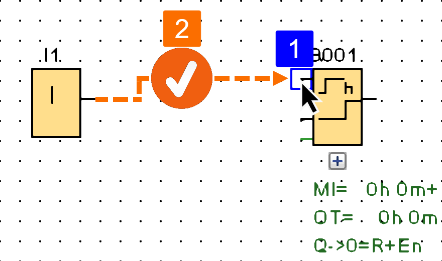
When a block input (pin) is connectable, the software will show a blue frame around your mouse pointer. This way, making it easy to identify available connections.
Conclusion on Siemens LOGO PLC Programming
In conclusion, Siemens LOGO Soft Comfort software is essential for programming Siemens LOGO PLCs. The software interface and its intuitive programming toolbar and menus make it easy for beginners to get started. On the other hand, its advanced features and functions cater to the needs of experienced programmers.
So far, you learned the basics of generating a new circuit program and selecting and placing blocks. You also learned how to configure blocks and establish connections between blocks. We have also discussed some practical tips and shortcuts that can help streamline the programming process. Once you follow these guidelines, you can create effective circuit programs to meet your specific needs.


