Siemens S7-1200 PLC Configuration - CPU Startup, Memory, Time, and Protection Settings
Introduction
CPU configuration is a critical step in ensuring the correct operation of the PLC and avoiding potential malfunctions. The CPU startup, memory, time of day, and protection and security settings all play critical roles in how the PLC will behave in various scenarios.
If you fail to configure these settings, unwanted consequences will occur, disrupting operations. So, it is necessary to have a solid understanding of these settings to maintain the smooth operation of industrial processes.
Prerequisites
What you will need to follow along with this tutorial are the following:
- The installation of TIA Portal software on your computer. We will utilize TIA Portal version 16 in this tutorial; however other TIA Portal versions are also acceptable.
- Understanding S7-1200 CPU digital IO settings
- Understanding S7-1200 CPU analog IO settings
CPU Startup Setting
To begin, navigate to the left pane and double-click the "Device configuration" item. It will open the PLC hardware configuration window. Next, double-click on the S7-1200 CPU to access the "Inspector window."
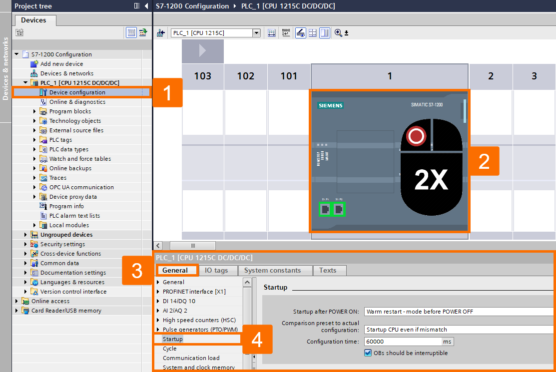
In the "Startup" section, settings related to CPU startup can be made, which can be the following:
Step 1: Startup after POWER ON. One of the significant settings of the CPU S7-1200 is to set its startup type after connecting the power supply. You have three settings for this purpose.
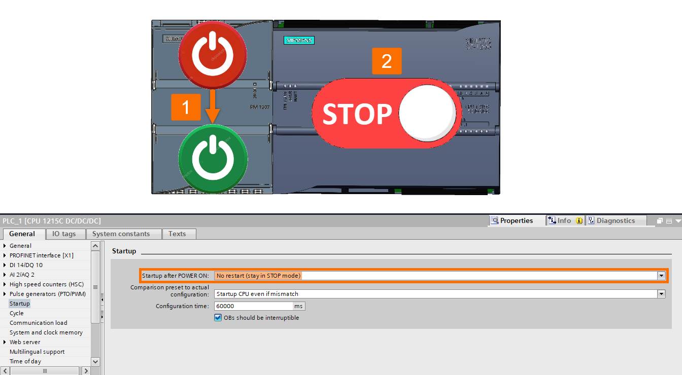
Step 1-1: No restart (stay in STOP mode). By selecting this option and after connecting the power supply, the CPU will be in STOP mode. In this case, you should set the CPU working mode to RUN through the TIA Portal software.
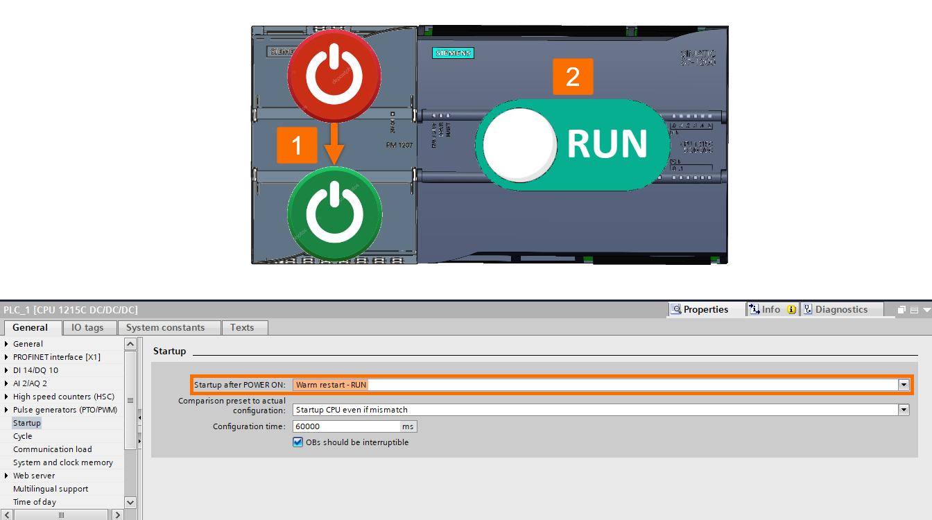
Step 1-2: Warm restart - RUN. By selecting this option and after connecting the power supply, the CPU will be in RUN mode. So, you don't need to reset the CPU working mode using the TIA Portal software.
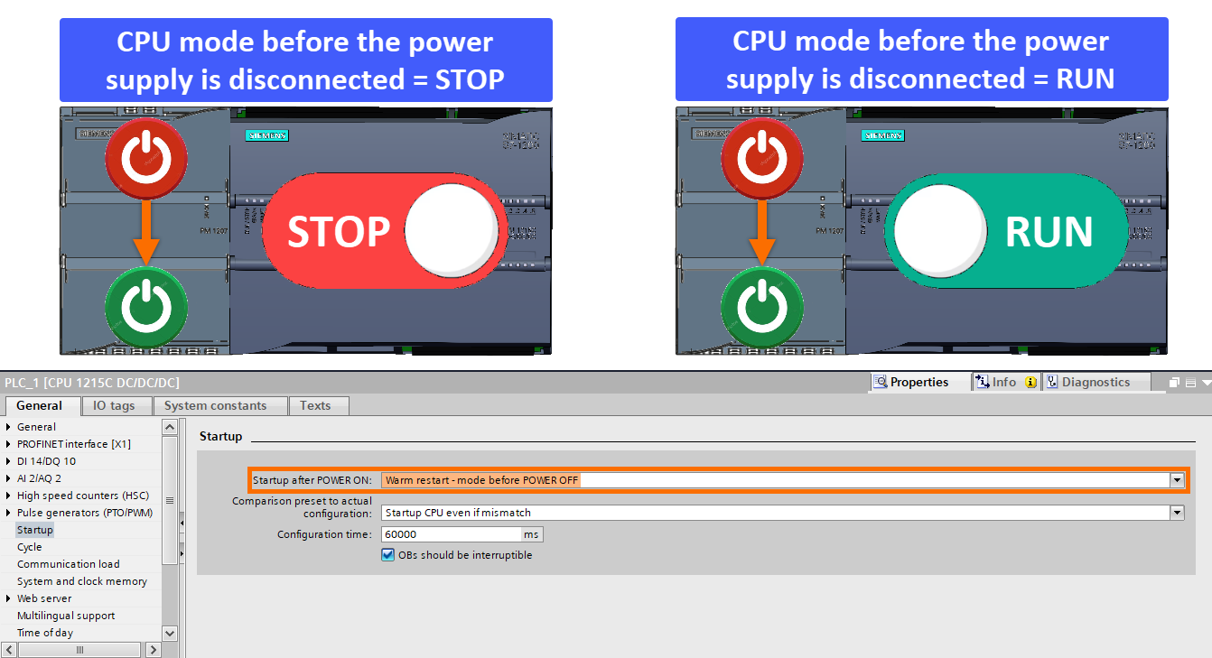
Step 1-3: Warm restart - mode before POWER OFF. By selecting this option, the power supply, the CPU will be in the last state before the power supply, For example, if disconnected. If the CPU was in the RUN working condition before the power supply was disconnected, it will be in the RUN working mode when you connect the power again. Likewise, if the CPU was in STOP mode before the power supply cut off, it will remain in STOP mode after the power is connected.
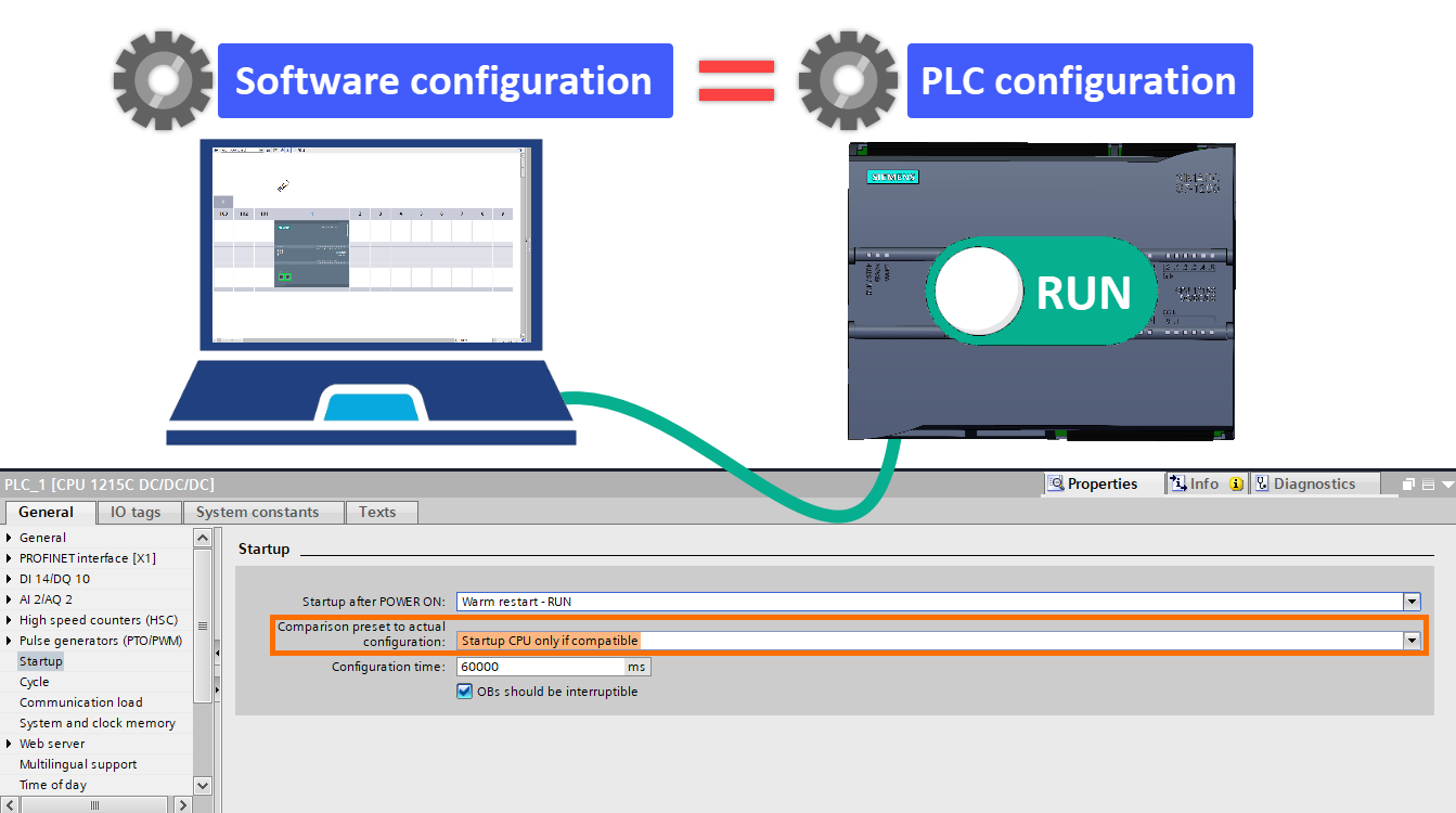
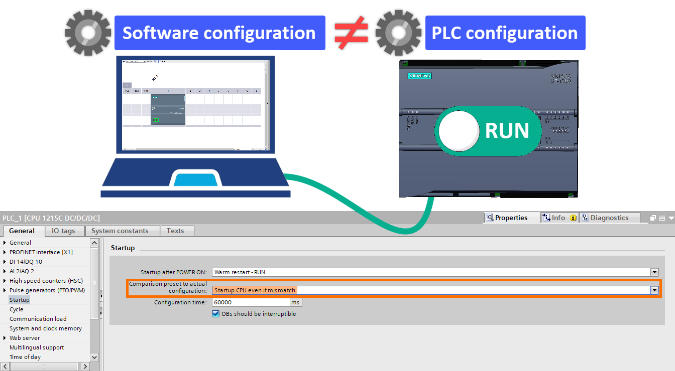
Step 2: Comparison preset to the actual configuration. Here, you can determine what happens if there is a configuration difference between the TIA Portal software and the existing PLC. Selectable options are:
Step 2-1: Startup CPU only if compatible. By selecting this option, the CPU will be in RUN mode if the configuration done in the TIA Portal software is the same as the actual PLC configuration.
Step 2-2: Startup CPU even if mismatch. By choosing this option, the CPU will be in RUN mode, even if there is a configuration difference between the TIA Portal software and the actual PLC.
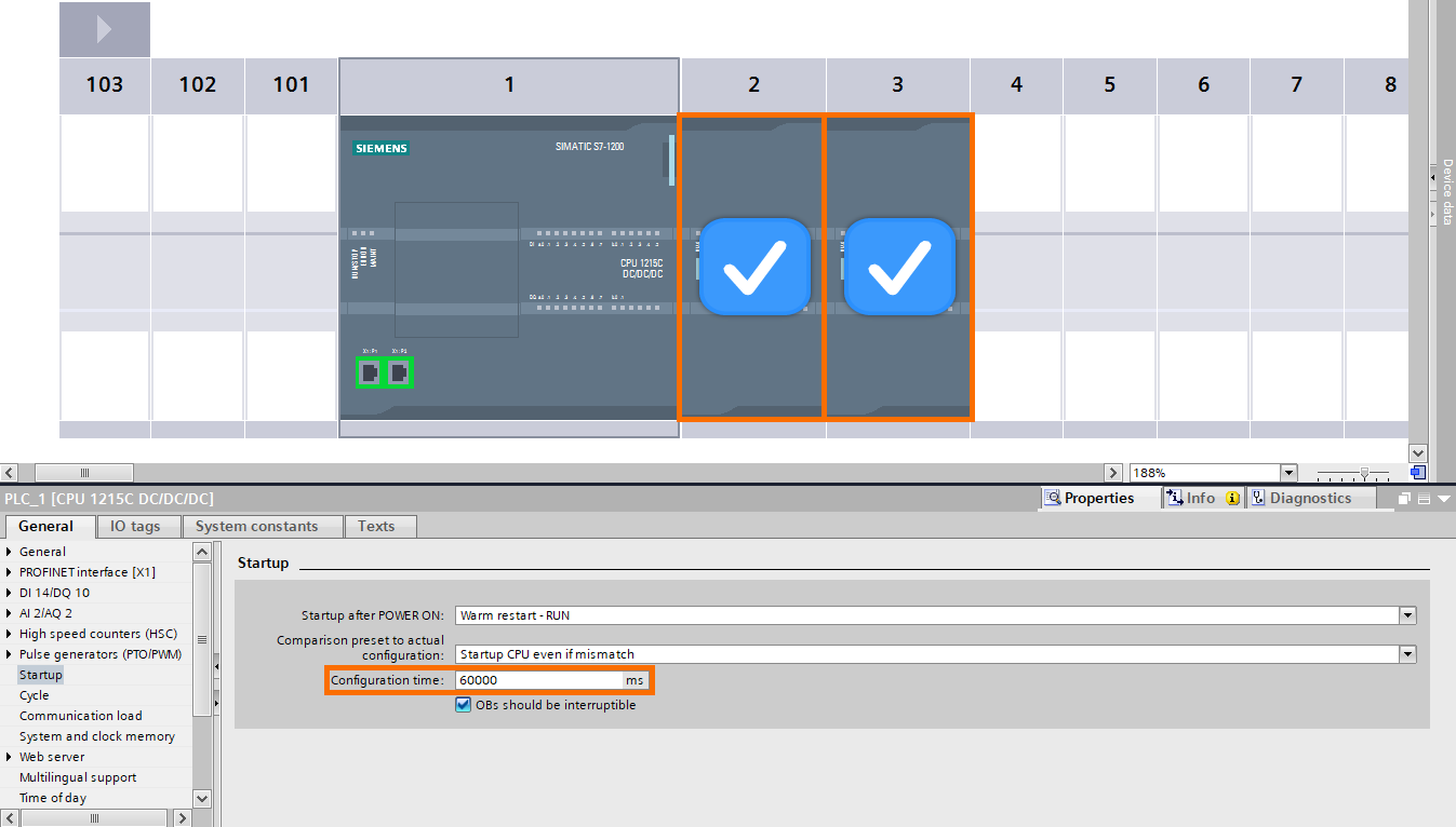
Step 3: Configuration time. It is the period that the IOs of the main rack and the expansion racks should be in startup condition and ready for operation.
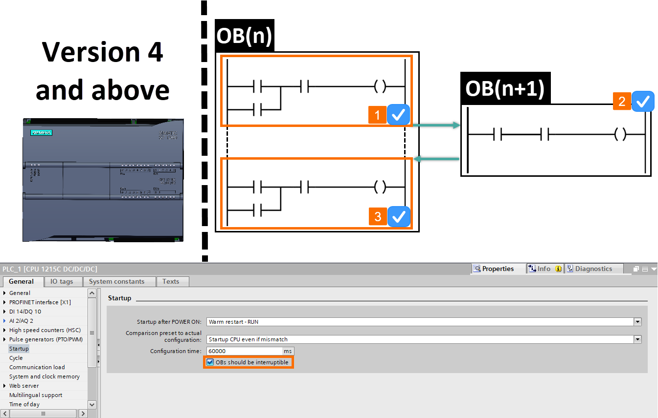
Step 4: OB should be interruptible. Different OBs have different execution priorities. OB1 has the lowest execution priority, and other OBs can interrupt its execution according to specific events.
In CPUs with a version lower than 4, what will happen if a higher priority occurs while one of the event-based interrupt OBs is running? Well, the new event OB is executed after the complete execution of the previous event OB.
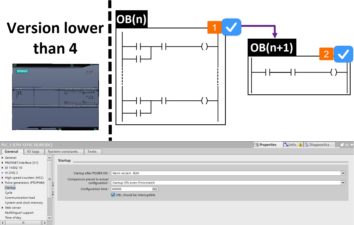
In CPUs version 4 and above, what will happen if an event with a higher priority occurs during the execution of an event-based interrupt OB? If the "OBs should be interruptible" option is activated, the execution of the previous OB is interrupted, and the new event OB is to be called. But, if the "OBs should be interruptible" is not selected, it makes the behavior of the CPU execute interrupts like CPUs with a version lower than 4.
CPU System and Clock Memory Setting
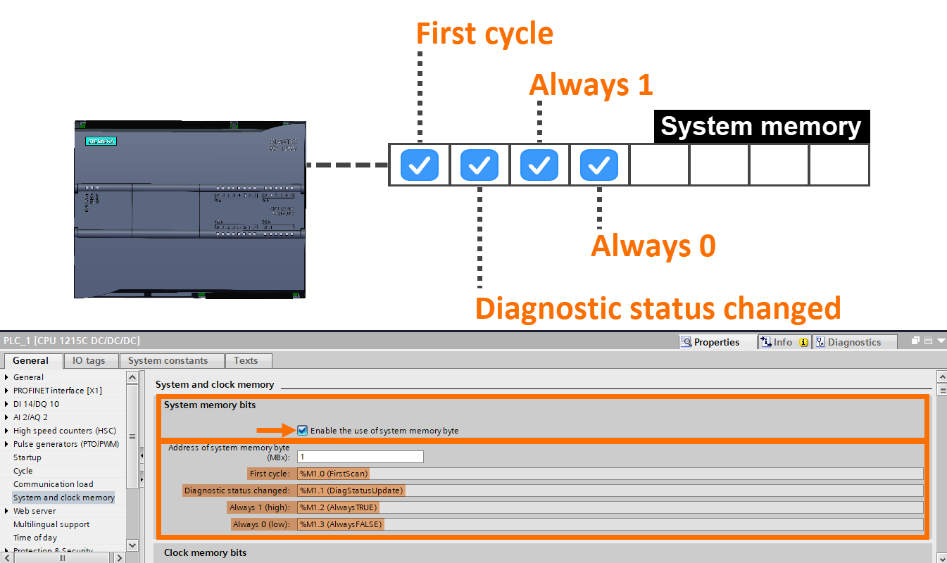
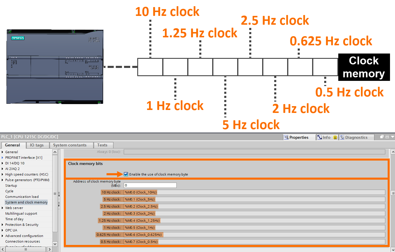
In S7-1200, one byte of CPU bit memory can be defined as clock memory (pulse) and one byte as system byte. If the System memory byte is activated, the "First cycle", "Diagnostic status changed", "Always 1", and "Always 0" bits are triggered. Each of them is assigned a bit address from the CPU bit memory. The user can use these variables in the program to perform specific tasks.
If the clock memory byte is activated, it will trigger a pulse byte (blinker). Each bit of this pulse byte starts on and off according to the frequency specified in its front.
CPU Time of Day Setting
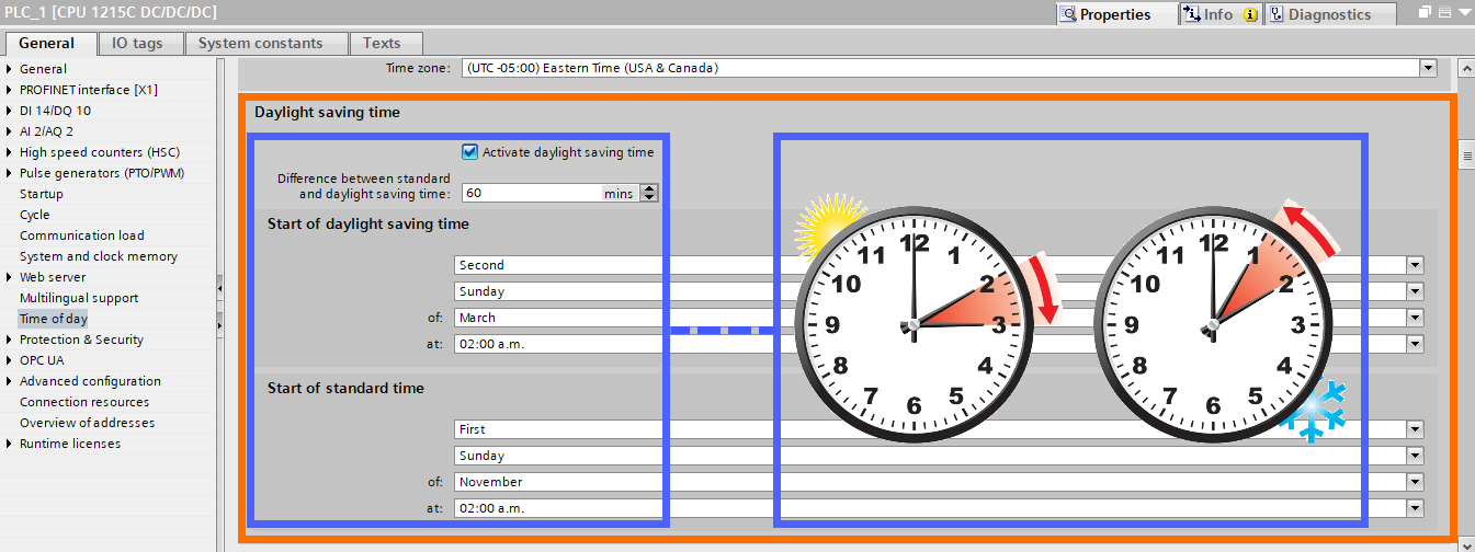
You can select the time zone and determine the automatic time change in the spring and autumn seasons for the S7-1200 CPU. To do these CPU time settings, refer to the "Time of day" section of the CPU setting.
In the "Local time" section and for the "Time zone" field, it is necessary to select the time zone. For applications within the US and Canada, you need to choose the "Eastern Time" option.
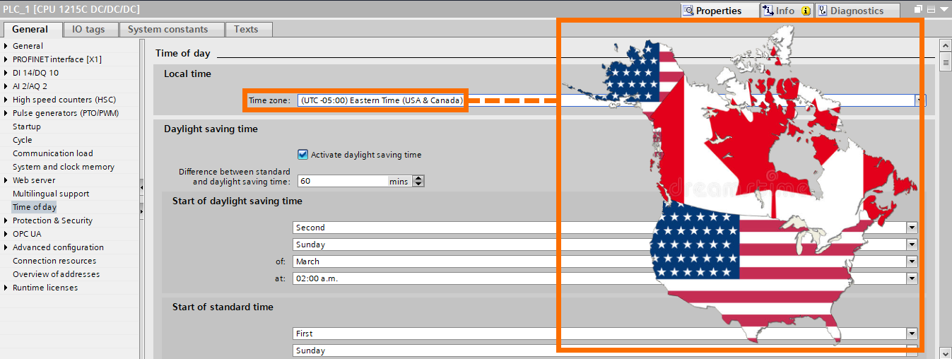
Also, in the "Daylight saving time" section, you can make settings related to the automatic shift of the CPU clock in the spring and autumn seasons.
CPU Protection and Security Setting
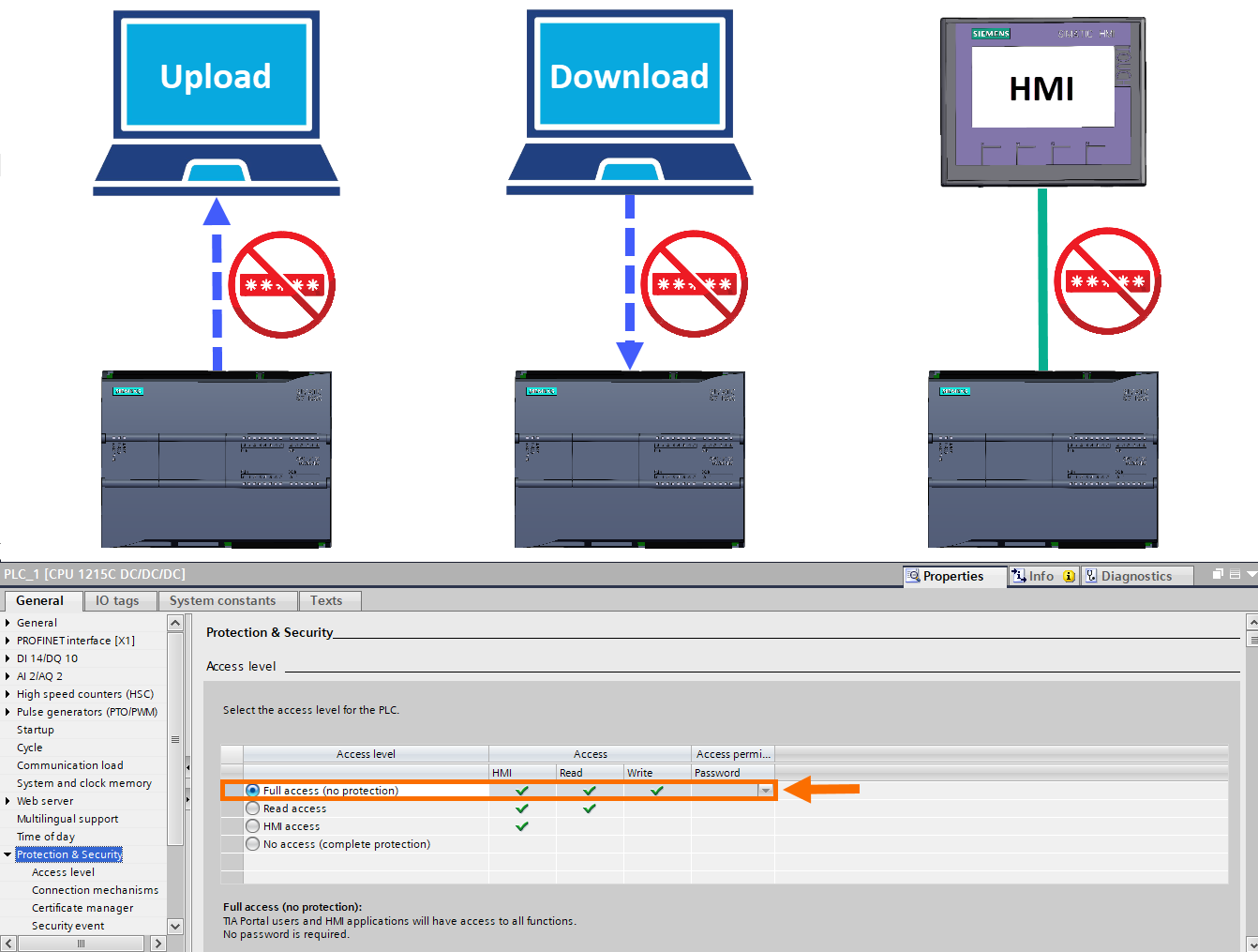
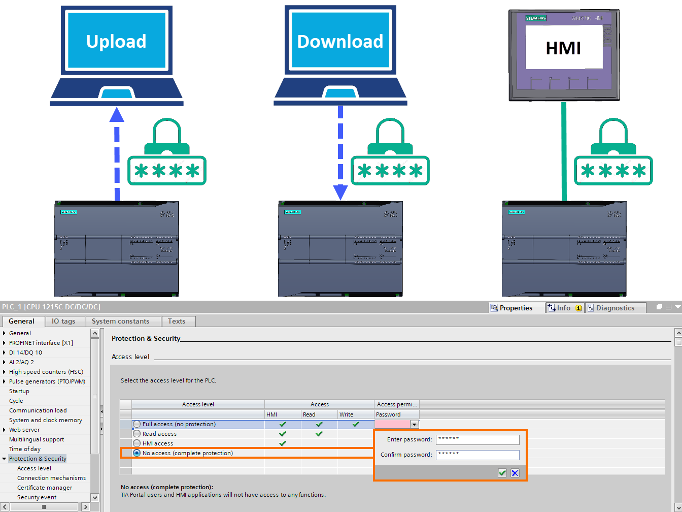
In this section, you can determine the settings related to deciding the level of access to the PLC. Also, you can choose the appropriate password if you want to download, upload, and communicate with the HMI.
Step 1: Full access (no protection). If you select this option, no protection level will be set to access the CPU to download, upload, and HMI communication with the PLC. Therefore, downloading and uploading can be done without entering a password. Also, the connection between the HMI and the PLC can be established without a password.
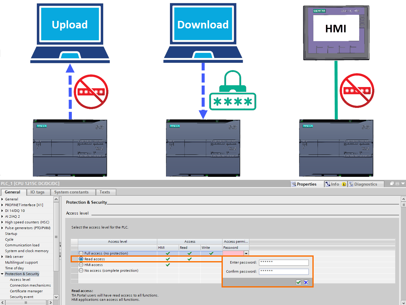
Step 2: Read access. By selecting this option, you can assign a desired password to the PLC and make the download dependent on the user entering the password. In this case, it is possible to upload to the PLC and communicate with the HMI without the need for a password. But once you want to download to the PLC, the appropriate password must be entered in the relevant box at the time of downloading. Note that the box for receiving the password is displayed at the required time (for example, during the download). So, the user must enter the correct password to perform the desired operation.
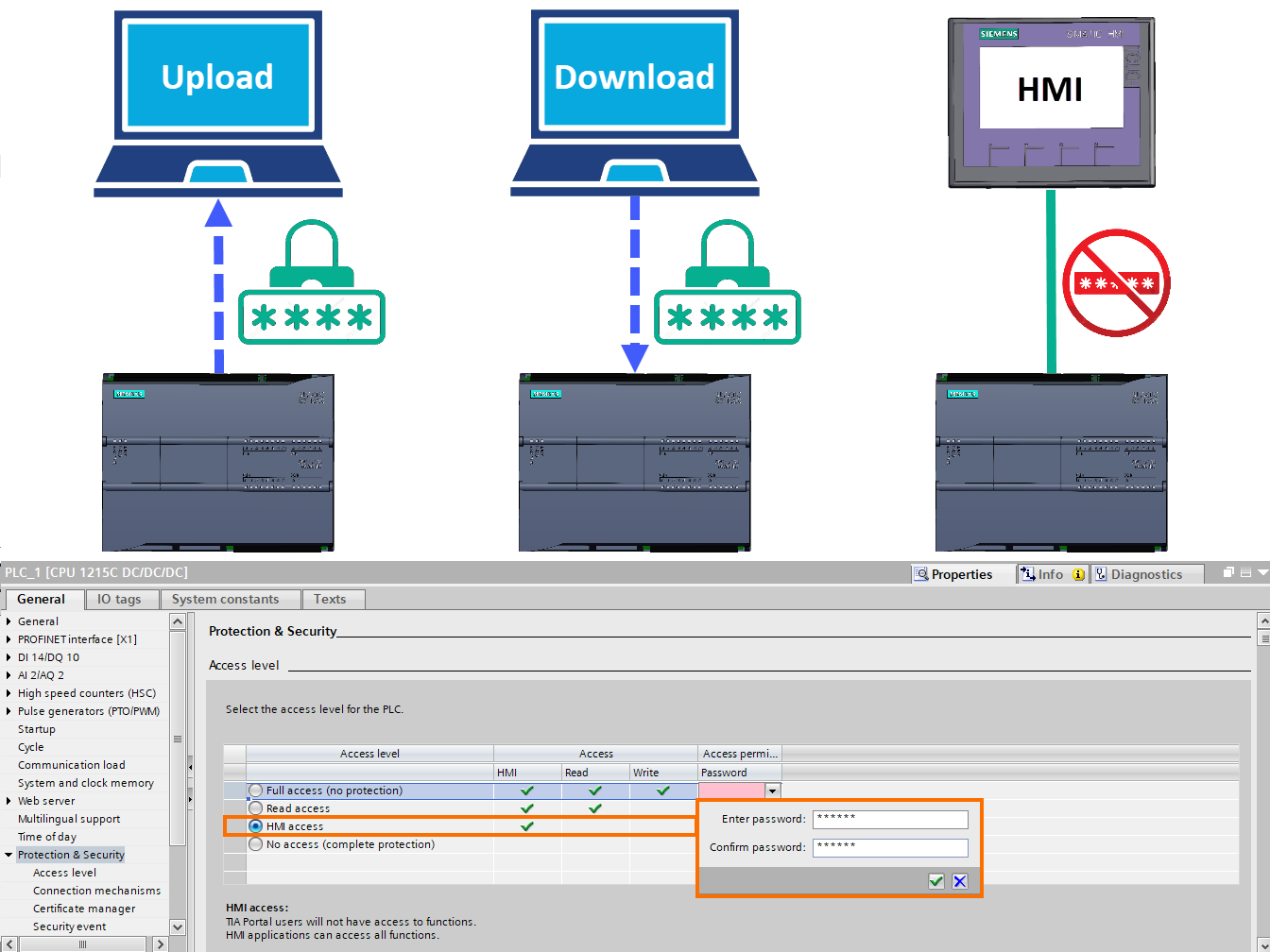
Step 3: HMI access. If you select this option, you can assign a desired password to the PLC. This way, download and upload operations will be dependent on the user entering the password. In this case, only PLC communication with HMI is done without a password.
Step 4: No access (complete protection). By selecting this option, the download, upload, and communication with HMI can be made dependent on entering the password by the user. In fact, by enabling this option, the highest level of protection for accessing the PLC is determined.
CPU Connection Resources Setting
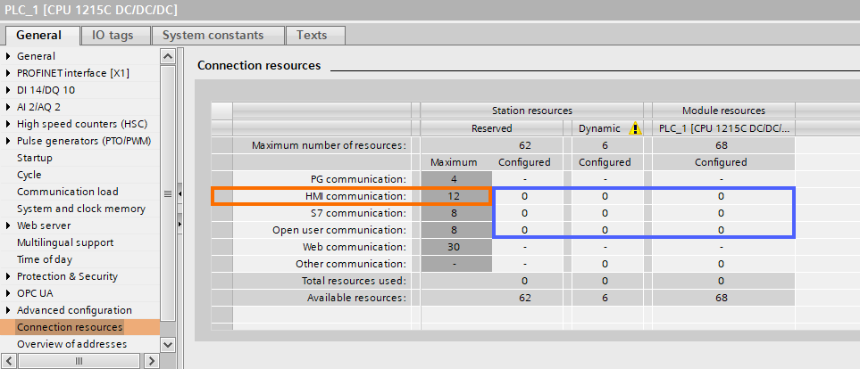
The number of allowed CPU connections to equipment through communication networks is shown in this section. Also, the number of configured connections is displayed as well. For example, for CPU 1215C, the number of links allowed to communicate with HMI is listed as 12 connections. Also, no communication connection is configured in this project.
CPU Overview of Addresses Setting
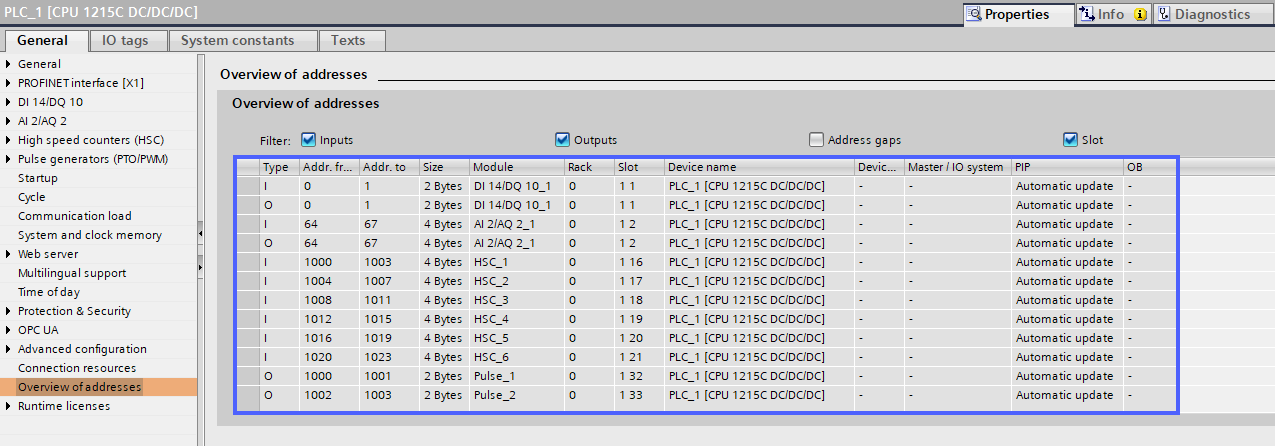
The addresses assigned to different parts of the PLC, such as input and output cards, high-speed counters, pulse generators, and ... are shown in this section.
Conclusion
In conclusion, the CPU startup, system and clock memories, time of day, and protection and security settings are crucial aspects of the S7-1200 CPU that need to be configured appropriately for the proper functioning of the PLC. Based on the specific requirements of industrial processes, these settings can be easily adjusted with the TIA Portal software. By selecting the appropriate settings for the CPU startup, users can determine the working condition of the CPU after connecting the power supply. System memory and clock memory settings enable the usage of specific variables in the program, while the time of day settings allow for accurate time synchronization. Finally, protection and security settings ensure the proper access level to the PLC while preventing unauthorized access.


