Speed and Position Control of Siemens Servo Drive Using TIA Portal

Introduction
SIMATIC S7-1500 PLC can seamlessly integrate with SINAMICS S200 PN servo drive systems to deliver unmatched performance, equipping users with precise position and speed control capabilities essential for achieving superior motion control in industrial automation.
In this tutorial, you delve into the intricacies of speed control via the SinaSpeed function block and learn about detailed instructions on achieving precise position control using the technology object.
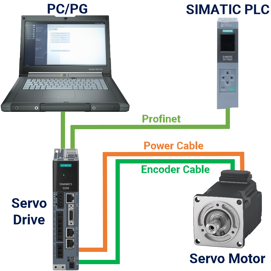
Figure 1.1 offers a visual representation that outlines the automation task, presenting a comprehensive overview of its structure and components.
Prerequisites
What you will need to follow along with this tutorial:
- You need to install the TIA Portal software on your personal computer. Although this tutorial refers to version 18, rest assured that other versions of the TIA Portal will work just fine.
- You need to be familiar with installing the GSDML file of your desired servo drive in the TIA Portal.
- You should know about adding the PLC and servo drive hardware to the project.
- You are required to install SINAMICS StartDrive version 18 SP2.
Servo Drive Speed Control: Hardware Setup
This tutorial section introduces the hardware configuration. Here, you are provided with detailed instructions to ensure successful implementation.
To get started, launch the TIA Portal software, create a project from scratch, and integrate the desired CPU, such as CPU 1511T-1 PN, into the project for further development.
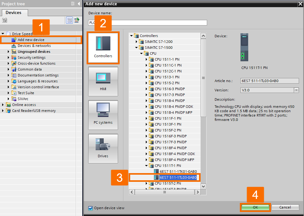
Double-click on the 'Add new device' item in the project tree to open the pop-up screen. Within the screen, choose the 'Drives' category and locate the desired S200 drives from the provided 'Drives & starters' list. Once found, ensure the firmware version is accurate and proceed to modify the device name to 'S200 PN'. Then, press the 'OK' button to incorporate the drive into the TIA project.

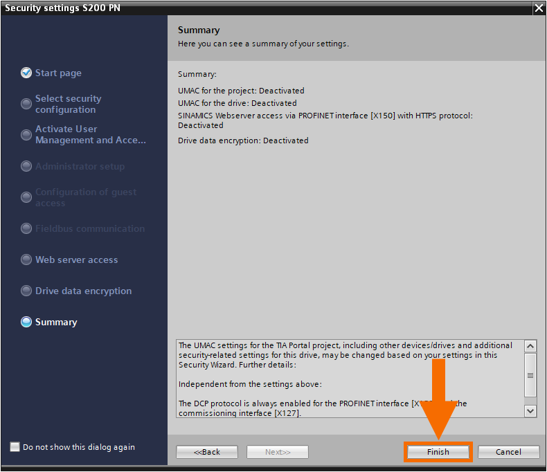
Disregard the security settings that are in place within this application, and instead, select the 'Continue with low-security settings' option to bypass any restrictions. Once the 'Warning' window appears, press the 'OK' button to proceed.

Finally, in the 'Summary' section of the security settings window, press the 'Finish' button to complete the process.
Once the servo drive 'Device configuration' window is displayed, navigate to the 'Device view' screen. From there, look for the recently added 'S200 PN' drive and select it. Proceed by clicking on the 'MOT' option, followed by 'Properties' from the Inspector window, and then choosing the 'Motor-selection-1FL2' item. Specify the desired power by inputting the target value into the 'Rated power' filter, or consider using alternative filters for customization. Scroll through the available motors using the scroll bar until you find the desired one, and then proceed with the selection.

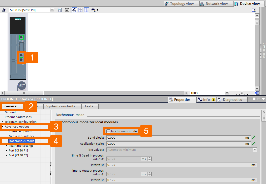
Click on the PROFINET Interface of the servo drive. Then, under the 'General' tab of the Inspector window, navigate through the 'Advanced options' to find and select the 'Isochronous mode.' Finally, uncheck the selection for 'Isochronous mode'.
Trigger the quick startup wizard by double-clicking on 'Guided quick startup,' granting you immediate access to an intelligently designed interface that will systematically guide you through each stage of the quick startup procedure. By assigning the responsibility of motion control from the PLC to the drive, you can activate the desired motion control functionality.
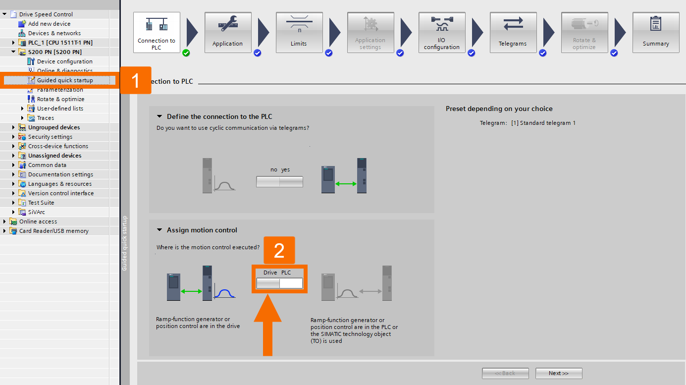
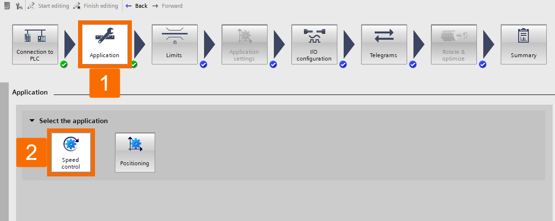
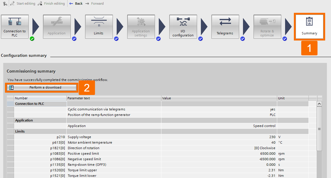
Choose the 'Speed control' option. This way, you can customize limits, telegrams, and I/O configurations to perfectly align with the application's specific requirements and operational parameters.
If you wish to download the offline configuration onto the servo drive, click the 'Perform a download' button under the 'Summary' tab.

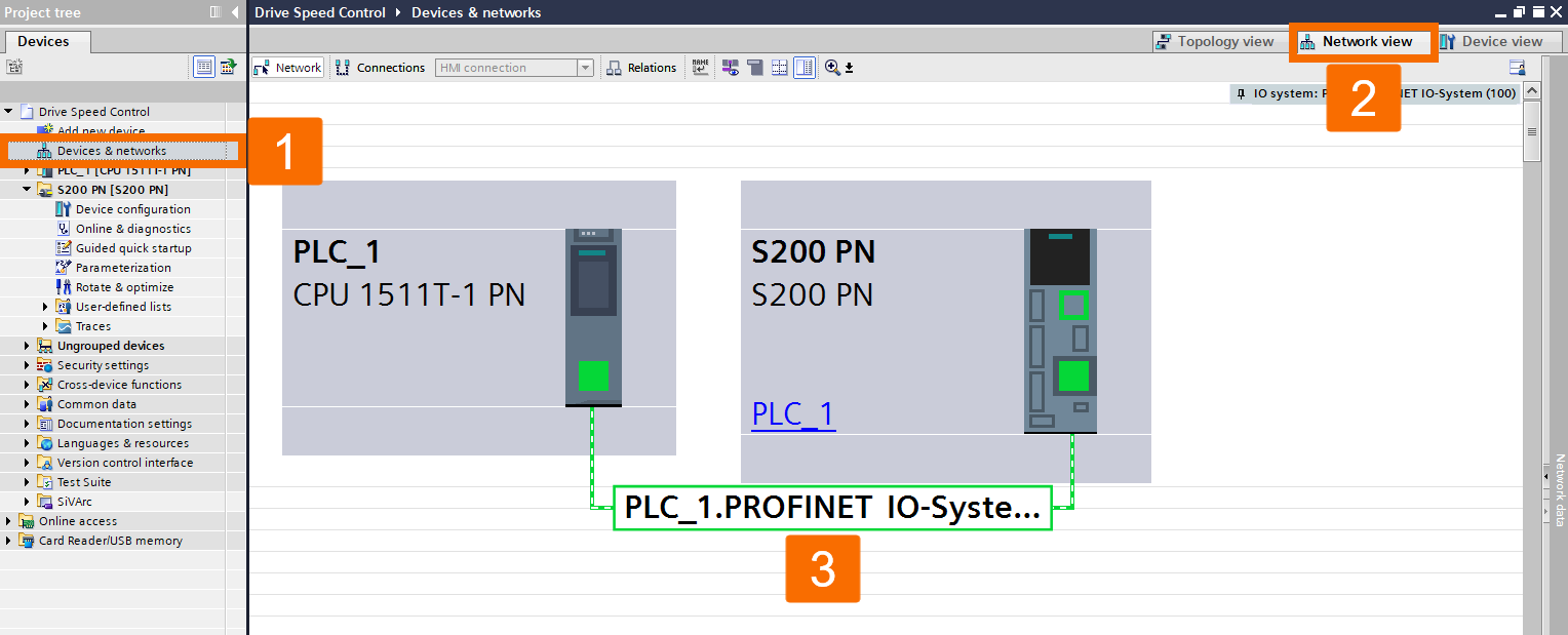
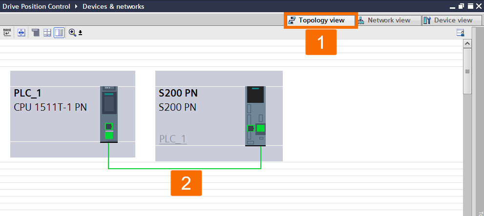
By double-clicking on 'Devices and networks' in the project tree, its window will appear. After that, transition to the 'Network view' and proceed with configuring the connection between the PLC and S200 PN drive.
Servo Drive Speed Control: PLC Logic
The main focus of this section is to provide a comprehensive guide on programming the logic of the PLC, ensuring users can effectively carry out the task.
Locate the Main OB1 (organization block) and open it to gain access. Once inside, you can select and move the SinaSpeed function block from the SINAMICS folder under the 'Optional packages' item within the 'Instructions' task card and place it into the designated area of OB1. After the 'Call options' window appears, left-click over the OK button to ensure that the background data block is incorporated into the project automatically.

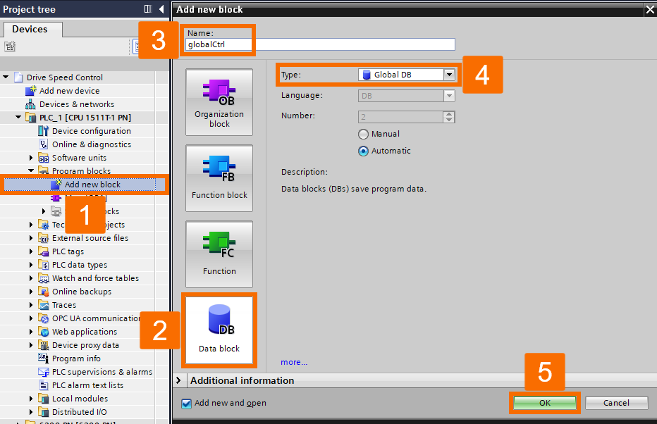
Double-click on the 'Add new block' under the PLC 'Program blocks' folder in the project tree, select the 'Data block' tab, give it a desired name, choose global as your data block type, and press the 'OK' button.
Establish the variables within the global data block that has been created. Following that, make the necessary modifications to the PLC logic to meet the desired requirements. After completing the compilation of the project, proceed to transfer and download it into the CPU of the PLC for operational deployment.

Servo Drive Speed Control: Execution
Within this section, you will gain an understanding of the procedures involved in operating the PLC logic.
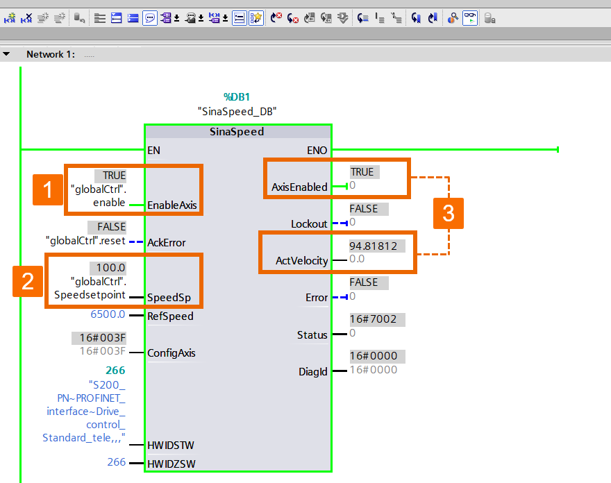
By pressing the eyeglasses icon, you can access a dedicated monitoring interface that provides real-time information and insights on OB1. By adjusting the speed setpoint to the desired value and enabling the axis, the drive will be activated, initiating the rotation of the motor.
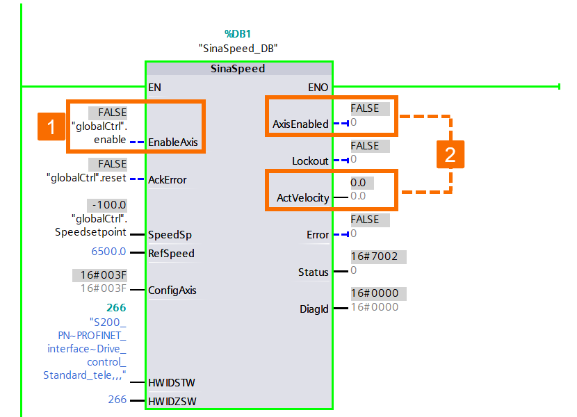
By adjusting the speed setpoint to a negative value, you can change the direction of rotation for the motor, thereby altering its rotational behavior.

By deactivating the axis, you will halt the rotation of the motor, causing the status of the 'AxisEnabled' to switch to FALSE, reflecting its deactivated state.
Servo Drive Position Control: Hardware Setup
Creating a project and incorporating the desired PLC, servo drive, and motor in the TIA Portal follows a similar approach to what you have previously learned in the section on speed control of servo drive.
Initiate the quick startup wizard by double-clicking on the 'Guided quick startup' feature. This action grants you access to a user-friendly interface that guides you through the necessary steps. One of these steps involves assigning the motion control functionality from the servo drive to the designated PLC. Furthermore, you can tailor the telegrams, I/O configuration, and limits to align with the specific requirements of your application.

For the offline configuration to be downloaded onto the servo drive, it is vital to left-click over the 'Perform a download' button found under the 'Summary' tab. This step is crucial to complete the process successfully.
Locate the 'Devices & networks' item on the left pane and double-click to open it. Once opened, transition to the 'Network view' and continue by configuring the connection between the S200 servo drive and the PLC, establishing a solid and reliable connection.

Transition to the 'Topology view' to begin the configuration procedure for the topology connection between the S200 servo drive and the PLC, enabling efficient network communication between the two components.
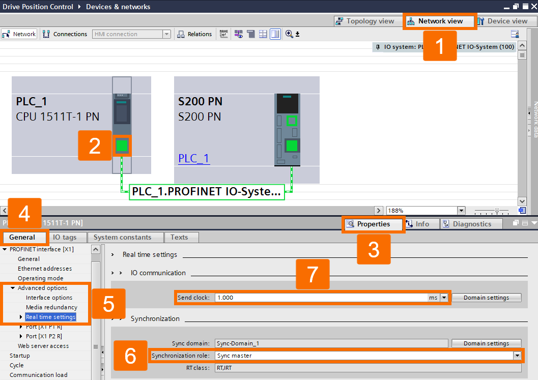
Move to the 'Network view' and locate the Profinet interface associated with the PLC. Proceed by choosing the 'Properties' in the Inspector window, followed by the 'Real-time settings' under the 'Advanced options' within the 'General' tab. In the settings, configure the 'Synchronization role' to 'Sync master' and ensure the 'Send clock' is set to 1 millisecond.
Servo Drive Position Control: PLC Logic
The main objective of this tutorial section is to familiarize you with the process of programming the logic in the PLC.
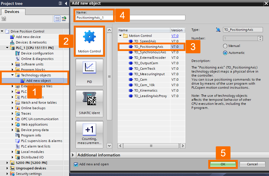
Locate the 'Add new object' under the 'Technology objects' folder within the 'PLC_1' in the project tree and then initiate a double-click to open it. Once opened, navigate to the 'Motion Control' category and opt for 'TO_PositioningAxis.' Proceed by modifying the name of this technology object, and finalize the process by clicking OK.
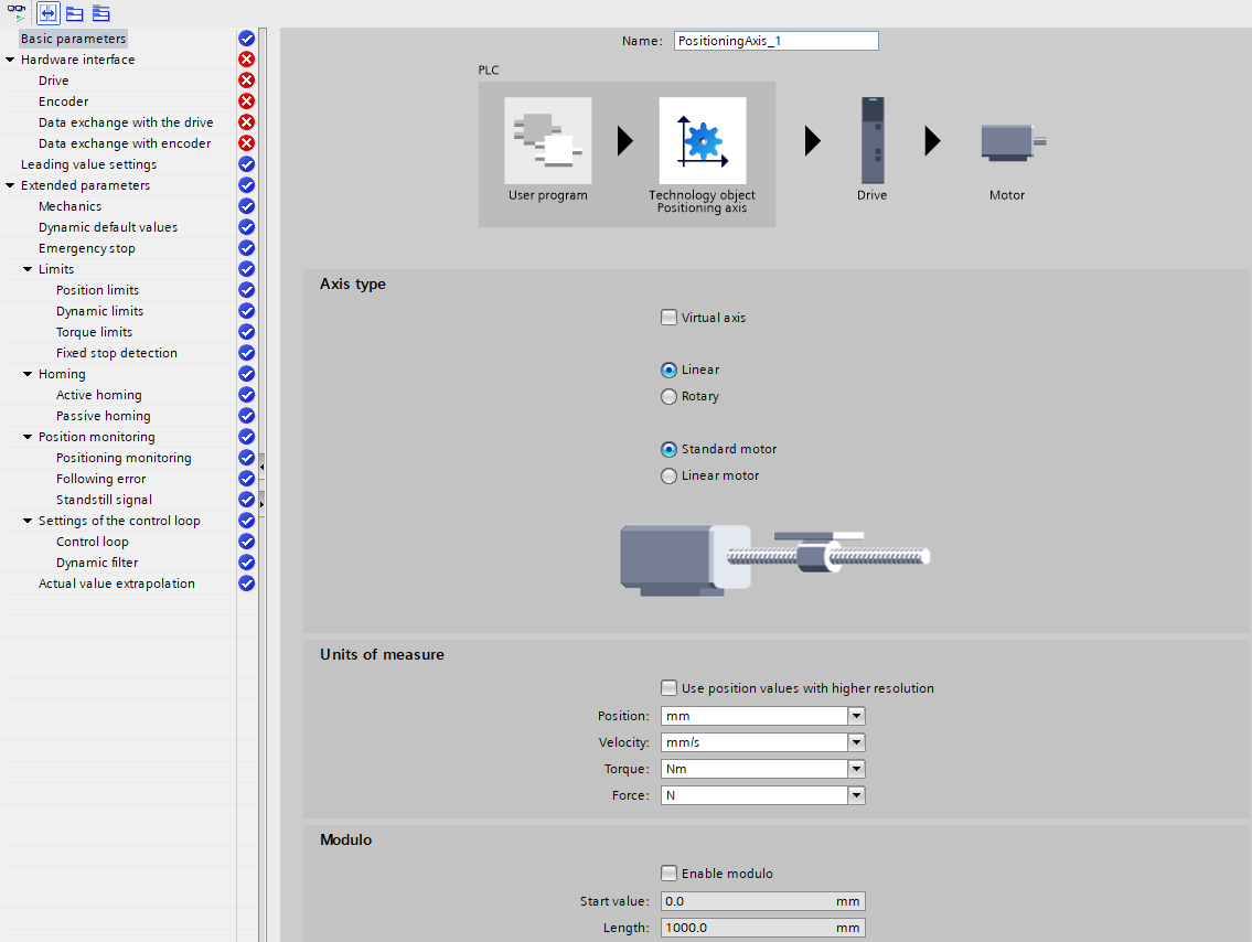
Upon opening the 'PositioningAxis' window, set the fundamental parameters to correspond with the specific requirements of the application being worked on.
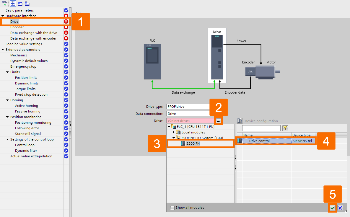
Locate and click on the 'Drive' item, then proceed by clicking the ellipsis (...) button to reveal additional options. Among the available choices, under the 'Profinet IO-System' folder, choose your desired drive. Once that is done, opt for the target device and confirm the selection by clicking the green check mark.
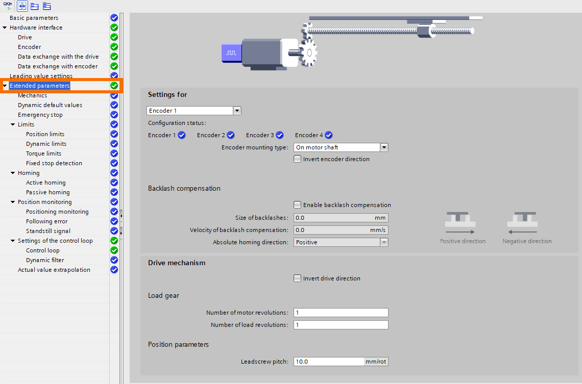
Within the 'Extended parameters' section, fine-tune the extended parameters to best fit the requirements of the current application scenario.
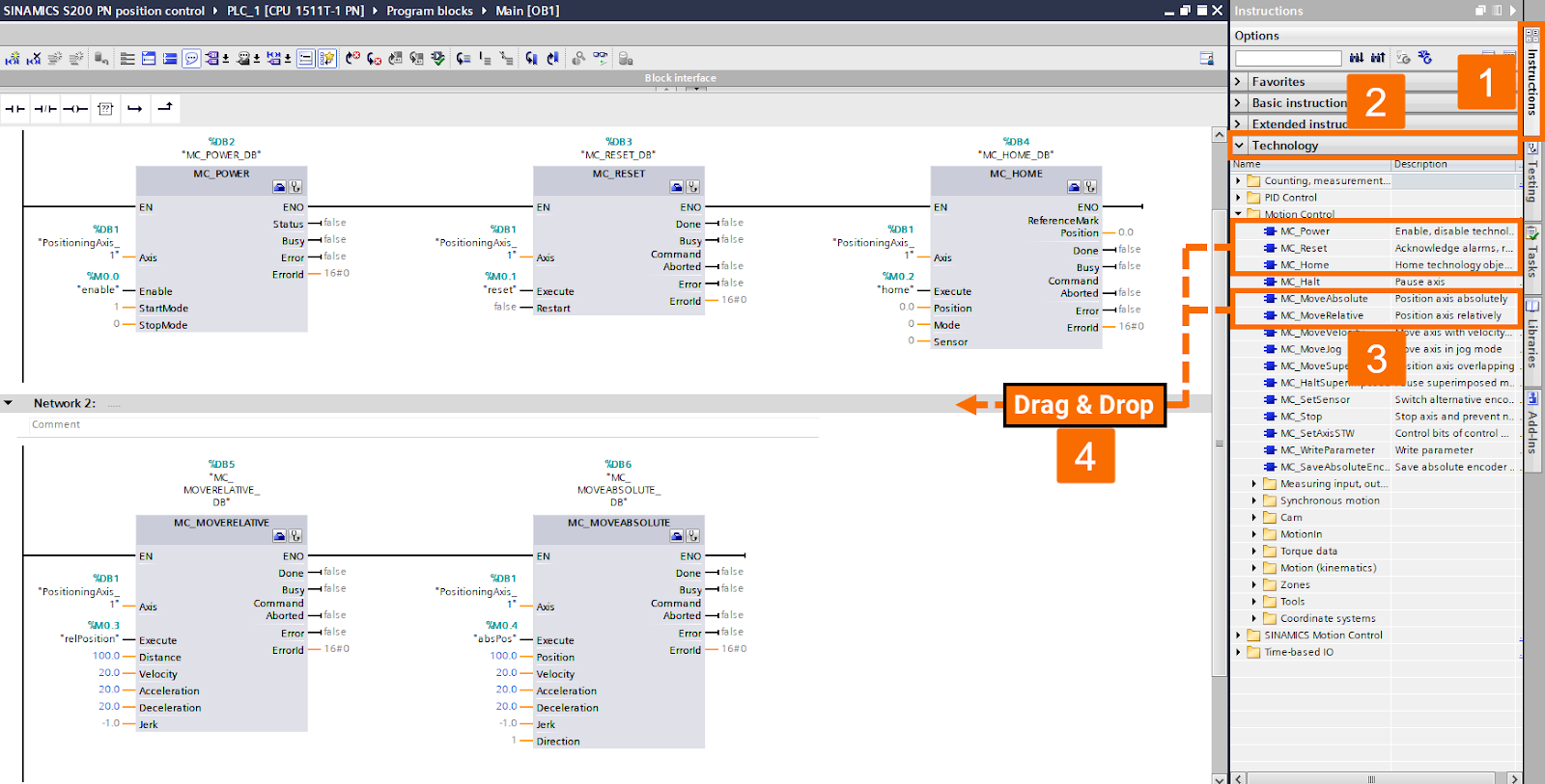
Locate the 'Main [OB1]' under the 'Program blocks' folder within 'PLC_1', and perform a double click to open it. Make modifications to the PLC logic to incorporate the necessary changes based on Figure 6.5. For this purpose, you can use programming blocks under the 'Motion Control' folder within the 'Technology' option on the 'Instruction' pane. Initiate the project compilation and subsequently transfer it to the PLC via downloading.
Servo Drive Position Control: Execution
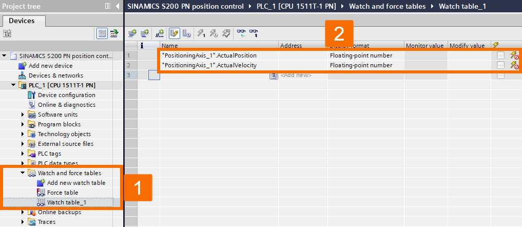
Generate a comprehensive 'Watch and force table' that allows concurrent monitoring of the created watch table and organization block, facilitating simultaneous observation and manipulation of data and program execution.
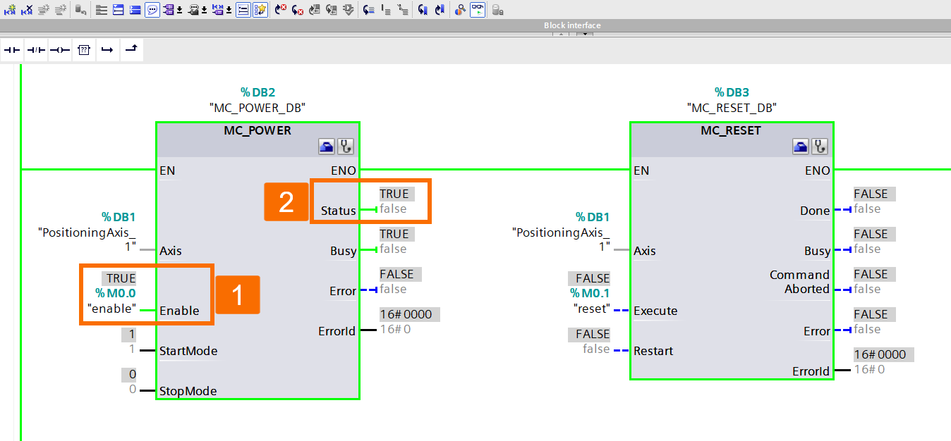
By utilizing the 'Enable' command present in MC_POWER, you can activate the axis, which subsequently causes the 'Status' of MC_POWER to be set to True.
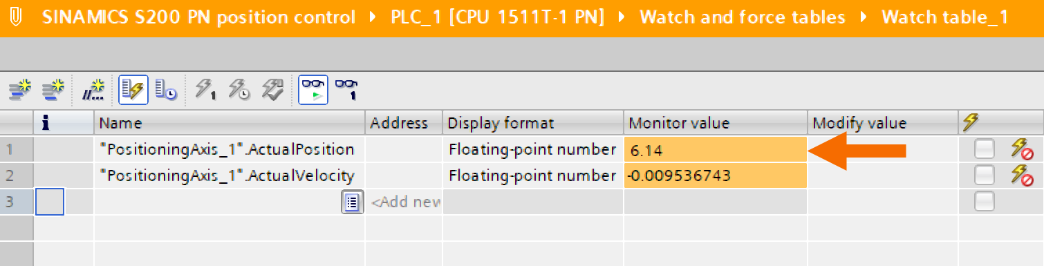
After enabling the drive, a positional reading of 6.14 is obtained in the context of this application, but it is worth noting that this value can vary in other applications.
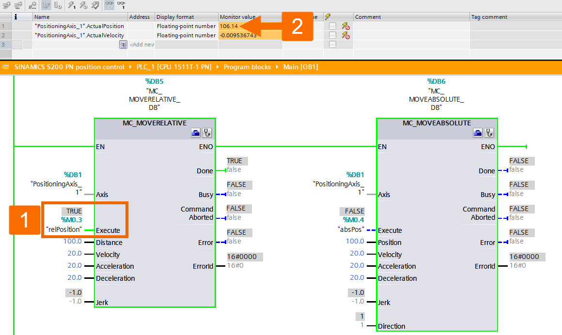
Initiate the execution of relative positioning, and once the position is completed, the resulting actual position is measured to be 106.14.
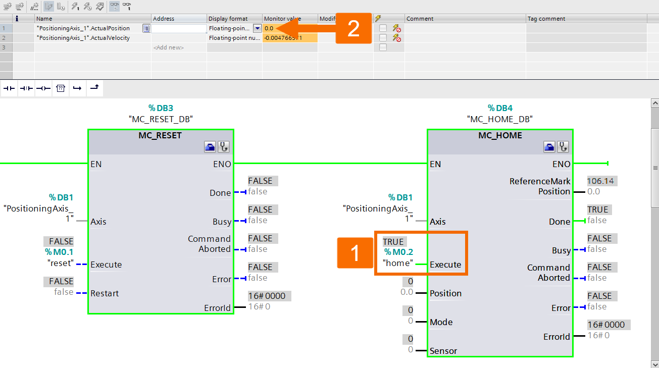
Initiate the execution of the homing process, and once the homing procedure concludes, the current position is measured to be 0.0.
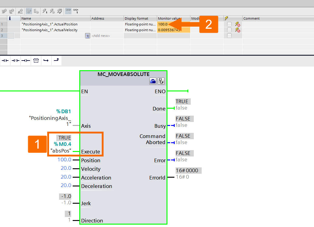
Initiate the execution of absolute positioning, and once the positioning task is completed, the resulting actual position is measured to be 100.0. The execution of absolute positioning is exclusively possible when the axis has achieved the homed status.
Conclusion
In conclusion, you learned how to control the speed and position of the Siemens S200 PN servo drive system using SIMATIC S7-1500 PLC hardware and TIA Portal software. These features empower automation engineers with the essential capabilities of precise position and speed control, enabling them to achieve exceptional motion control and elevate their industrial automation operations.
