Point IO 1734 Allen Bradley - Tutorial on Programming Inputs Outputs in RSLogix Studio 5000 Ladder

Introduction
In the previous tutorial on Point IO, we’ve installed a SICK Sensor onto the 1734-IB8 input 0. We’ve also tested the sensor, input as well as the software to make sure that the data is sent to our PLC as expected. Now that we’ve established this link, we need to spend some time programming the input and going over a simple example of how it can be utilized in a practical application.
A photo-eye, such as the one we’re working with, is mostly used for a presence or absence application. In other words, it will send a digital high signal when something is in front of it and a digital low when it’s not detecting anything. This application has a wide range of uses such as counting objects, detecting valve positions, detecting system conditions, detecting levels, detecting failure conditions, etc.
In this article, we’re going to explore the application of said sensor as a box counter. It will increment a software counter as a box travels in front of it. Based on this information, the programmer may create conditions for a pallet routine, for a backup, etc.
Point IO Input in RSLogix Studio 5000
The data from a Point IO node will come directly into a pre-populated PLC scoped tag. Each module within the node will have a separate tag along with individual input and output tags.
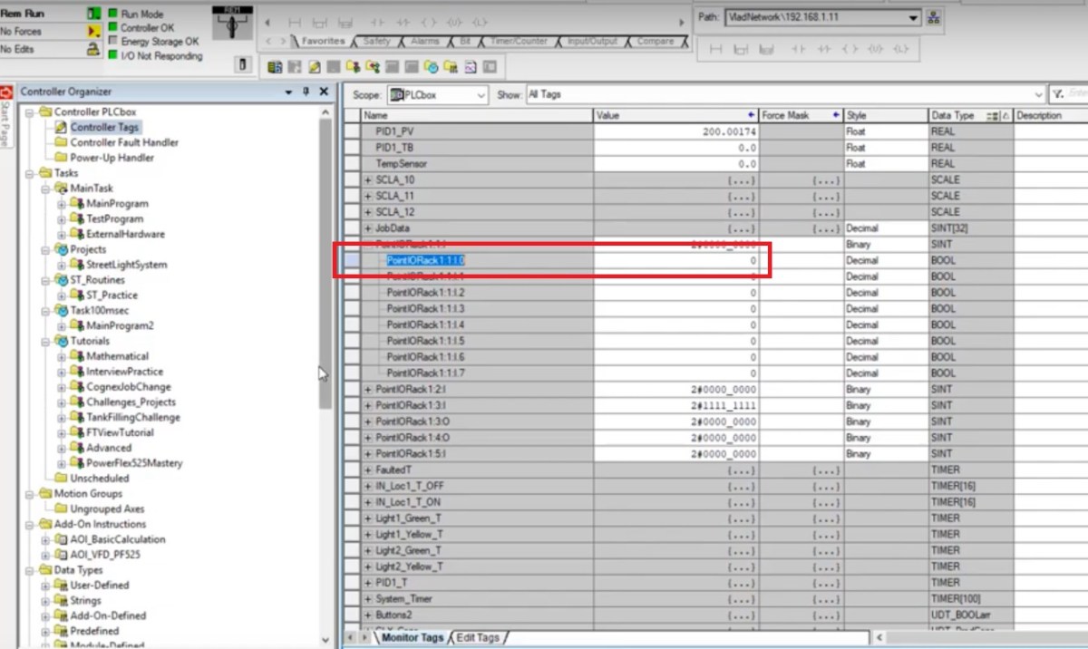
The 1734-IB8 input card we’ve used for the SICK Photo-Eye is listed as PointIORack:1:1. By expanding the Input section, we will find the exact input we’re using as shown in the image below. Note that as you add modules into the Point IO rack, they will be numbered according to the slot they’re located in. If you decide to re-arrange the modules, you’ll need to re-configure the IO Tree and make sure that you migrate the tags accordingly.
The tags associated with each input or output can be used directly within the PLC program. However, it’s a much better idea to create an explicit routine for the inputs and outputs in which they are mapped. This practice allows for a much simpler testing procedure, makes it very obvious as to where the inputs and output are coming from and makes sure that the system is easy to modify in the future. We will be looking at how to implement this in the sections belo.
Mapping Inputs for Point IO Slot 1734-IB8
We’re going to use the “_02a_Inputs” routine for mapping the inputs tied to Slot 1 of the Point IO rack. In a similar fascion, we should map every single input card within this routine.
The first input (Input 0) is tied to the tag PointIORack1:1:I.0. It’s mapped through an XIC Instruction and tied to the PLC scoped tag IN_Loc[0] through an OTE Instruction. Although the rung is simple, it accomplishes a very important task: passing the input from the input module to a tag used internally within the PLC. By doing so, the programmer can easily change the input used for the sensor without having to go through the logic and modifying every single instance of the tag. The need for this procedure most often occurs when an input is no longer working and needs to be migrated to a different slot.
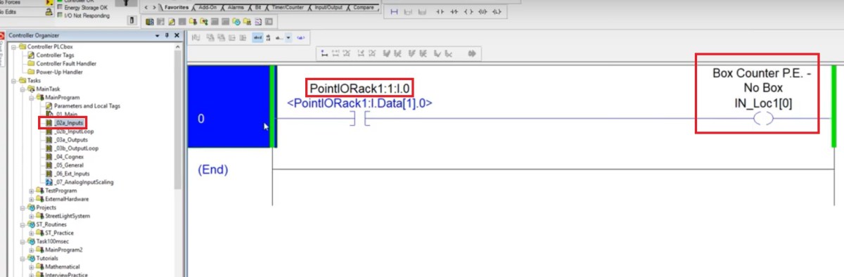
Note that we’ve also added a comment onto the local tag in order to identify the device associated with it: Box Counter P.E. – No Box.
Since we don’t have any devices tied to the other inputs as of right now, it’s advised to create the structure without giving any descriptions to the other tags. It’s also acceptable to label them as “SPARE” to let those who will use the software afterwards know that these tags weren’t specified for any field devices. Here’s the pre-compiled implementation of the logic.
Simple Photo Eye Box Counter Ladder Logic
Now that we have the photo eye tied to the input on the Point IO rack, we can write some simple logic to count hypothetical boxes passing in front of the eye.
The tag used within the CTU Counter rung is the debounced version of the input. Since we had already tied the input to a local tag, it’s easy for us to apply any logic to it.
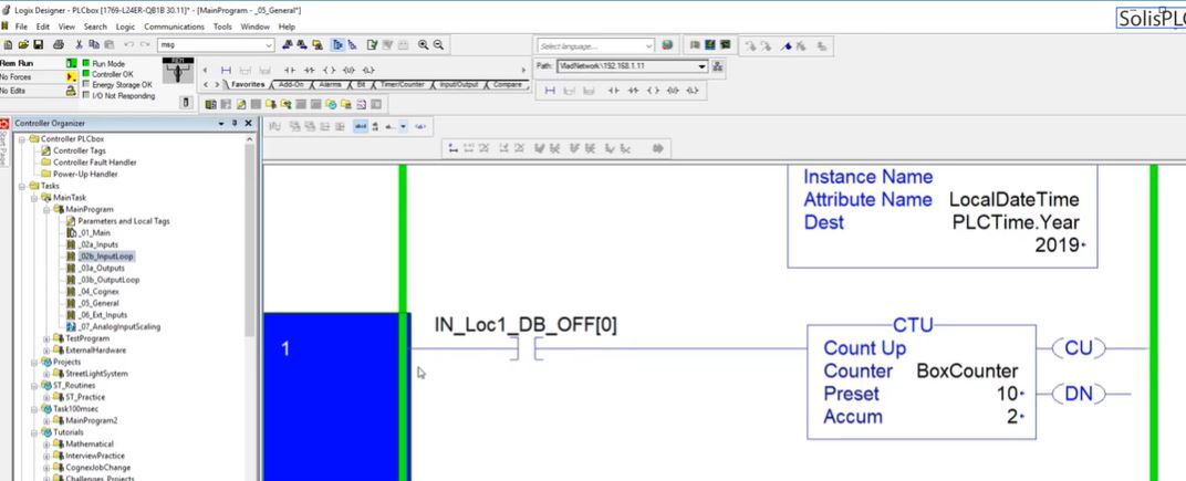
As the box passes in front of the sensor, the input will transition from high to low. On the PLC, the logic will transition the IN_Loc1_DB_OFF[0] tag from low to high and increment the timer by one.
For example purposes, you may use the BoxCounter tag to send a .DN bit to a separate part of logic in order to see when a certain limit is reached. The limit is represented by the “Preset” variable set within the counter. An example of this would be a set number of boxes which need to transition into a pallet, a specific number the line needs to complete, etc.
Conclusion
An input is tied into the Point IO block and is utilized for counting the presence of objects on a production line. This simple example introduced us to the use of a digital SICK sensor, the use of Point IO as well as best practices in ladder logic.
The application can be extended to sensors from different families, sensors of different types and other devices such as relays.
