Bit Masking Tutorial - MEQ | Masked Equals Instruction PLC Programming Bit Manipulation Optimization
Introduction
The MEQ or the Masked Equals Instruction allows for efficient bit manipulation in PLC programming. This instruction was covered in one of our previous tutorials, but we’ve received many questions with regards to the functionality of MEQ and a request to incorporate it into an example.
In this tutorial, we will be looking at a PLC routine that is used for recipe manipulation. By using this logic, it’s possible to switch between multiple valves that are required only in certain recipes and not in other ones.
Do note that the example is fairly basic to convey the point across. An actual recipe routine would include many more elements, fault checks, additional valves, an interface to an HMI and more. The goal of the demonstration is to demonstrate how the logic within the first implementation can be translated into a much more condensed and customizable version through the use of a bit-mask. Furthermore, note that this could have been implemented in a different manner; as always, there’s more than one way to implement every functionality.
Picking a Recipe through Bit Manipulation
The most basic way of building a recipe control system begins with the user picking a recipe. In our case, we have a single rung of logic which is connected to a “virtual HMI” system. Through this system, the operator is able to select a recipe number that we’ve limited to 10.
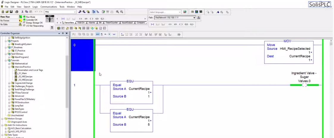
Based on the recipe selected, 1 through 10, a different set of valves would be energized. For the purposes of this tutorial, we’ve limited the number of valves to 6. Furthermore, the valves can be thought of as ingredient feeders. You have sugar, salt, spices, chocolate, honey, etc. In other words, every recipe has a set of ingredients that should be fed into a larger batch.
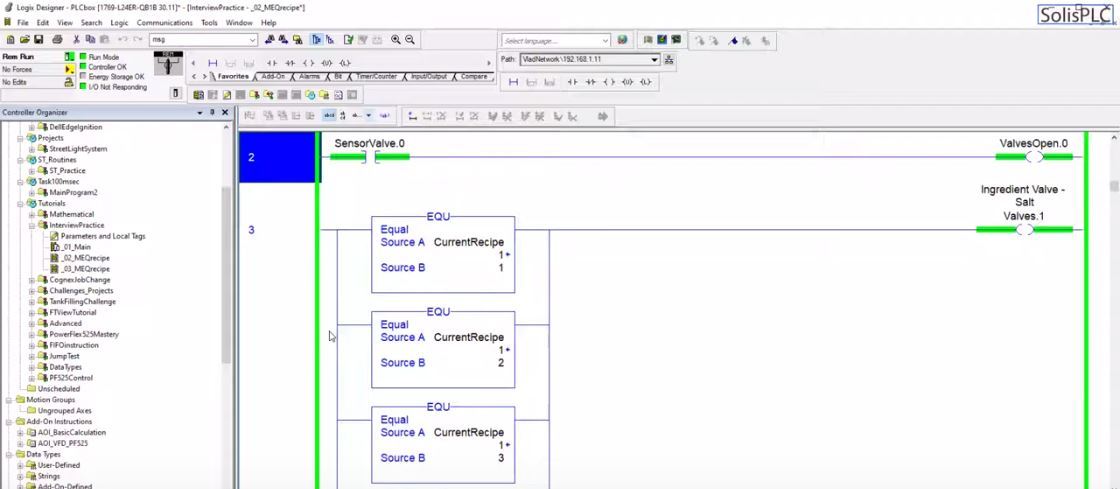
The next important piece, as shown above, is a set of “ValveOpen” bits. These are validations of the status of every valve.
The logic is such that our system will request certain valves based on the recipe to open and then perform a check only on those valves to make sure that they did open. This practice is common in the field as valves may stick, be forced open or closed through mechanical means or they’ve lost their air supply (in case of pneumatics). This may also be due to a cleaning or sanitation process of that specific piece of equipment while another recipe is being run. In short, it’s always best to have feedback in order to have confirmation of the state.
In the actual program, the SensorValve bits are simple local bits that I’ve toggled back and forth in order to validate the logic.
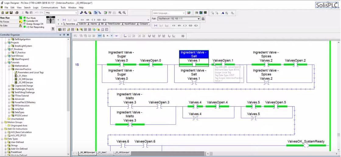
The next piece of the routine takes what was described above and issues a “System Ready” bit when the appropriate valves for the recipe have been opened. As the rung above dictates, each valve can be either selected or not. If it’s not selected, we don’t care about it. If it is selected, the appropriate “ValveOpen” bit must be energized. If that’s not the case, the “System Running” bit will not be energized through the OTE Instruction thus indicating to the operator that the system isn’t ready for this recipe.
Using Bit Masking / Manipulation
The logic above will work just fine. However, it does create several problems based on the way it’s implemented.
- Modifications are complex – If the PLC programmer was asked to add a new recipe, he’d have to introduce a new set of branches around every Valve rung. He also has to create the logic associated with any new valve or other external device added to the system. The process would be tedious, costly and prone to errors.
- The flow is difficult to visualize – The logic layer out in the program is split into multiple rungs and spans for over 20 rungs total. A programmer may condense this by using branches, but he’d still be left with a long program that isn’t very easy to follow.
Instructions such as the MEQ, MOV, COP, and BTD are used for bit manipulation and address the problems outlined above. These instructions reduce the complexity of the code, allow a much easier sequence of adding a new recipe and save on the implementation time. Lastly, by using these instructions, the user may much easier verify what has been added into the system.
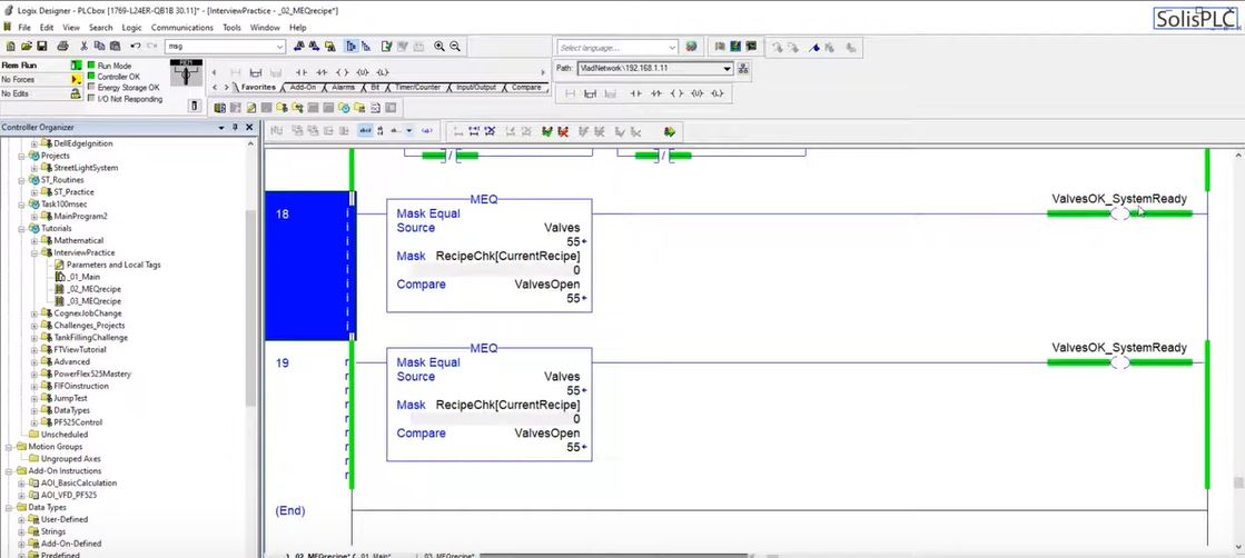
The MEQ instruction is the perfect solution to replace the “System OK” logic. It can be applied to the recipe and the currently open valves to compare that the valves that have to be open are open. In this case, the Valves are the Source elements and are compared to the ValvesOpen element. The Mask is created based on the recipe requirements and contains the information for each recipe in the form of an array.
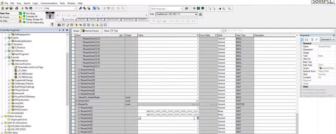
To create the mask for the MEQ Instruction, we have to edit the array of tags we’ve created. To simplify this task, we can switch the double integer from displaying in decimal to binary. In this view, we can see every bit of the double integer. By setting the bits of the valves that we need to account for in each recipe, we can create an array of recipe checks to use for the instruction. In other words, if the first recipe calls for Valves 3, 4 and 6 to be open, the first 8 bits of the mask would be 00101100.
Conclusion
Through effective bit manipulation and the use of appropriate instructions such as MOV, COP, BTD, MEQ and others, it’s possible to reduce implementation time, simplify the logic and cut costs of introducing new parameters into the system.
The MEQ instruction is an important tool that allows the programmer to compare two containers based on a specified mask. The mask allows the program to dynamically select which bits of the two containers will be checked. In other words, an EQU Instruction will compare every bit of the two items while the MEQ Instruction will only compare the bits that are set to “1” within the spacified mask.


