Festo Servo Motor Tutorial - Integrating the CMMT-ST Festo Drive into RSLogix Studio 5000 PLC AOI
Introduction
In the previous tutorial on Festo CMMT-ST servo drives, we’ve installed the tools, connected to the drive and set up all the required parameters to get our system going. In this tutorial, we’re going to focus on connecting the drive to an Allen Bradley CompactLogix PLC, establishing a control scheme through an Add-On Instruction (AOI) and validating the tag structures passed between the two devices.
Downloading and Installing EDS and AOI Files
In order to accomplish the above, we’ll need to download two files from the Festo Support Portal: the Electronic Data Sheet for the drive family and the Add-On Instruction that contains the implementation of drive handling in RSLogix and Studio 5000 software.
Step 1 - Download and Install EDS files
Navigate to the Festo Support Portal and search for “cmmt-st-c8-1c-ep-s0” or “8084006” which is the part number for the hardware.
Navigate to the “Software” tab.
Download the “EtherNet/IP EDS” folder.

To install the EDS files, we need to start by extracting the folder that was downloaded. Right click the folder and select “Extract All”.
Within the folder, you’ll find a “.eds” file and an icon for the device.
Launch “EDS Hardware Installation Tool” (A software package installed along with RSLogix and Studio 5000).
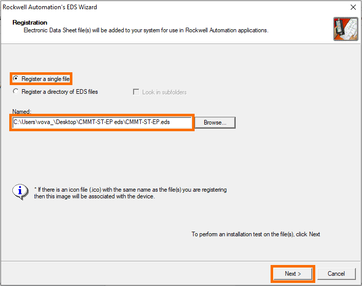
Select the path to the file you’ve downloaded and click on “Next” as shown below.
What are EDS Files?
It’s important to understand the purpose of .eds files when working in the Allen Bradley environment. These files contain the information for a specific device and allow the user / programmer to work with various external hardware components. In general, the RSLogix 5000 and Studio 5000 programming environments will come with an installation of most (currently available .eds files). This includes the various PLCs, HMIs, variable frequency drives, IO modules and more. However, as new modules are released, the programmer will need to import the associated .eds files manually. In other words, the version v20 of RSLogix 5000 may not install all the latest files needed to work with recent hardware; it’s up to the programmer to find them and install them.
As shown above, it’s common for programmers to create a master folder into which they paste all the new .eds files and specify the path for the “EDS Hardware Installation Tool” to import all of them at once.
Other tools, such as RSLinx, utilize the EDS library of the programmer. Once installed, the devices will show up accordingly.
Step 2 - Download and Install AOI files
An Add-On Instruction, or AOI is a function definition that can be used within RSLogix or Studio 5000. These functions contain custom code that was written by a 3rd party (Rockwell in certain cases) and are used to facilitate development and use of equipment. In this case, the manufacturer of the servo drive has provided the end-users with an AOI that is used to receive and send data between the PLC and Servo Drive.
From the same location as described above, download the following file which contains the AOI structure as well as examples of use cases.
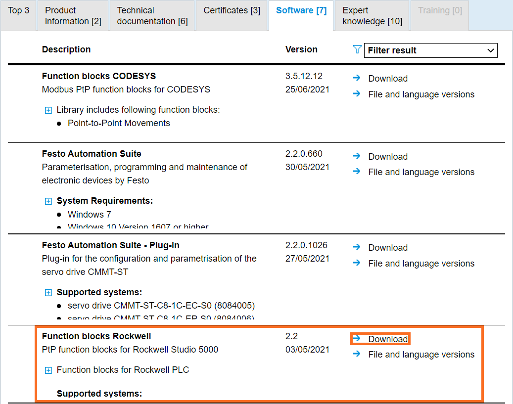
Note: although the file is labeled as “Function blocks Rockwell”, the AOI implementation is usable in any language, including ladder logic.
Right click the folder and select “Extract All”.
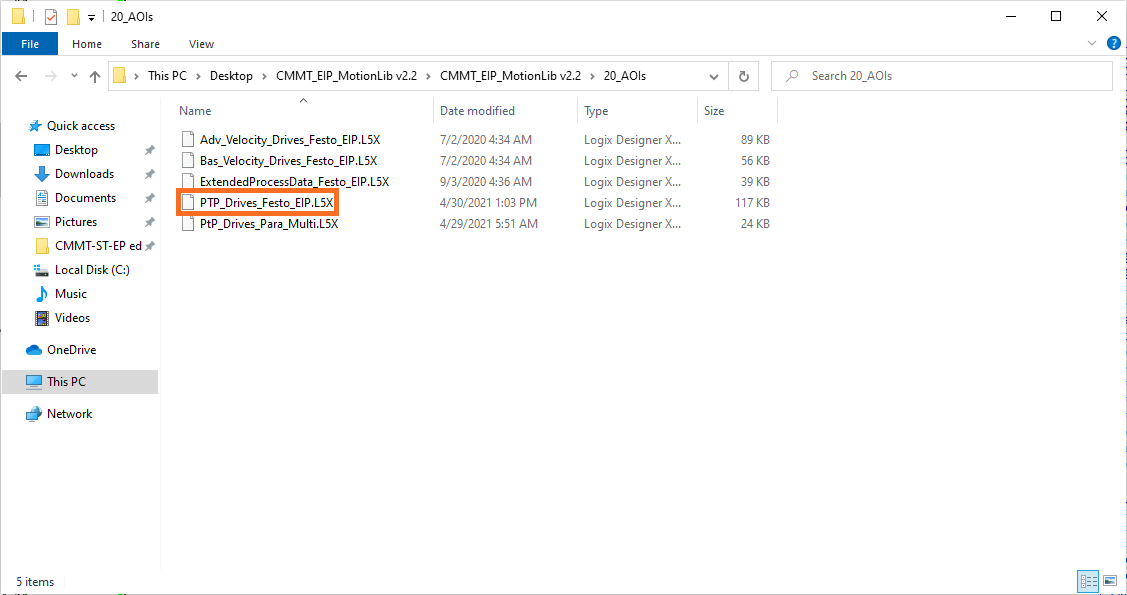
As mentioned above, in addition to the AOIs, you’ll find supporting documents within the folder. The following AOI files will be available to the user. The specific drive family we’re working with will utilize the PTP_Drives_Festo_EIP.L5X file.
Installing an AOI in RSLogix or Studio 5000
From within the RSLogix or Studio 5000 environment, in an open project, right click on “Add-On Instructions” in the Controller Organizer and select “Import Add-On Instruction…”
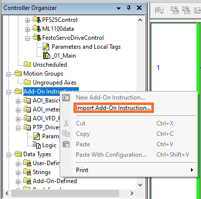
Choose the file we’ve specified above and click on “Import”.
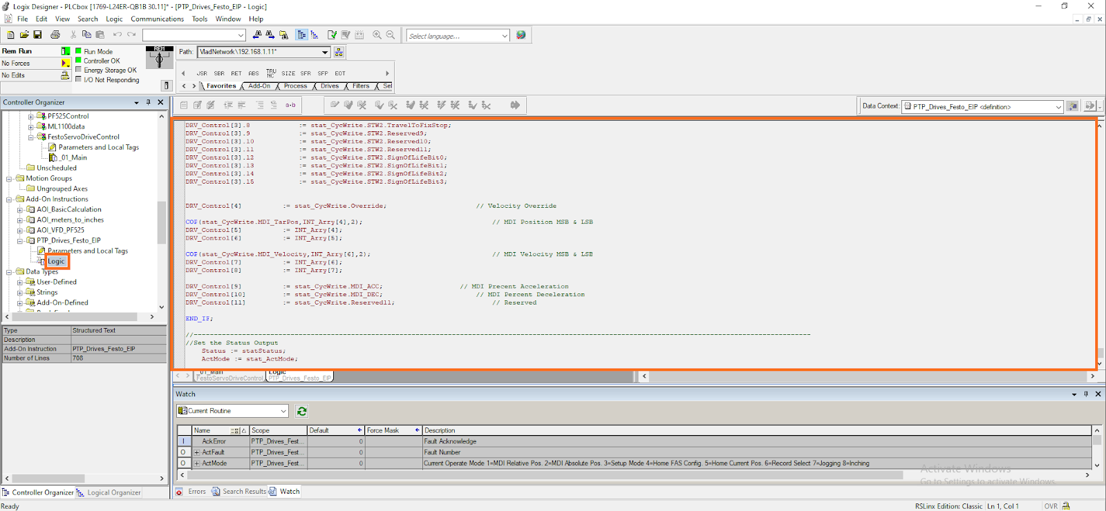
At this point, you can choose to review the logic that was written by the OEM for this specific drive. We don’t recommend that you make any changes to this implementation, but it may be useful in understanding the flow of data within the function. To view the logic, open the AOI and select the “Logic” file in the Controller Organizer.
Step 3 - Create an Instance of the Drive
Now that we have all the components in place, we can add the drive to the program.
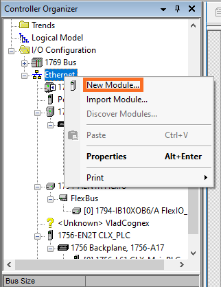
Under “Ethernet” in the Controller Organizer, select “New Module…”
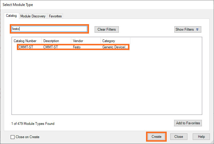
From the next menu, locate the module for which we’ve installed the .EDS file. You can do so by searching for “festo” in the search bar.
Press “Create”.
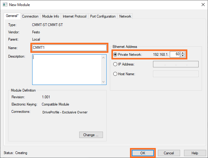
In the next prompt, give your module a unique name and IP address.
Press “OK”.
Now that the module is connected over Ethernet to the PLC, we can use the AOI to pass the data to and from the drive.
In the desired program, add two COP instructions that will be used to convert data from SINT to INT arrays and configure them as shown below.

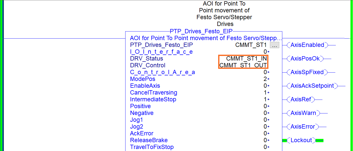
Add a new instruction to the rung and make it of type “PTP_Drives_Festo_EIP”.
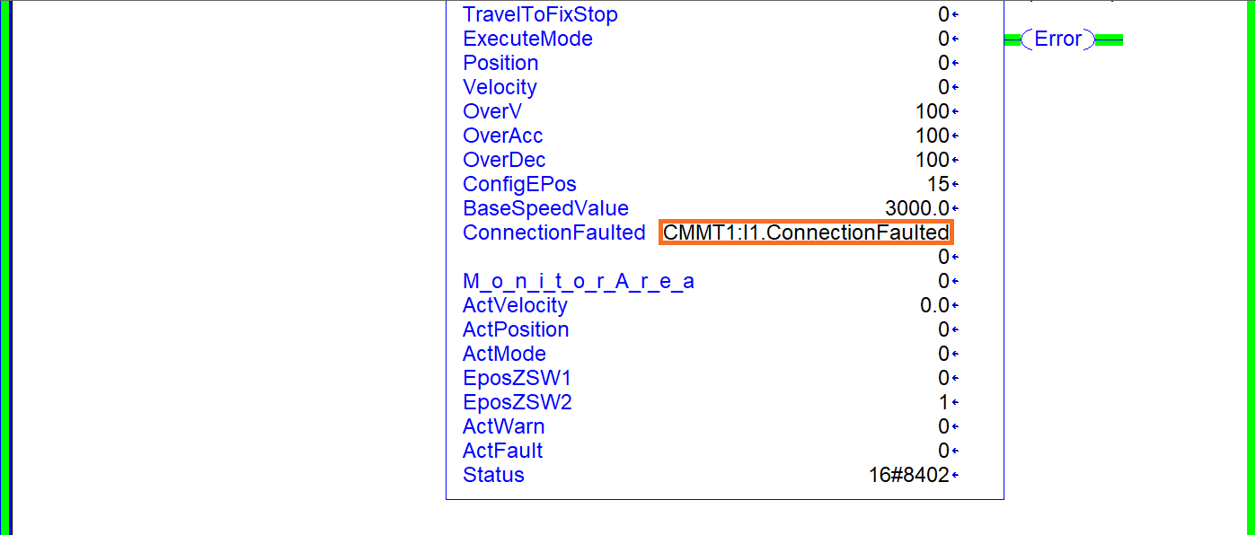
We’ll need to specify the parameters that are critical to the AOI: DRV_Status, DRV_Control, and ConnectionFaulted.
The DRV_Status and DRV_Control registers have been created using the COP instructions. The ConnectionFaulted bit can be pulled directly from the output of the drive.
Conclusion of Festo CMMT-ST Servo Drive to CompactLogix Connection
We’ve installed the EDS and AOI files for the drive and connected to the module over Ethernet from the CompactLogix PLC. At this point, we can pass data to and from the drive using the Studio 5000 environment.


