How to Install, Configure, and Program a Schneider Modicon M241 PLC

Introduction
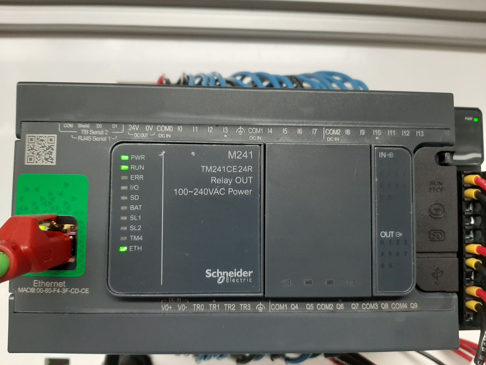
Modicon M241 is a brick-style machine PLC with onboard Inputs and Outputs. It comes with different options for communication such as Modbus and Ethernet (Modbus TCP) protocol. The software used to program this PLC is EcoStruxure Machine Expert V2.0 which is available on the Schneider Electric website to download and can be used as a free trial for 45 days.
In this tutorial, we will cover Schneider Electric Modicon M241 PLC and CFC (Continuous Function Chart) Programming in EcoStruxure Machine Expert. You will learn how to install, configure and program the M241 PLC in Machine Expert Software.
Downloading the EcoStruxure Machine Expert Software
To get started, click this link and download the software.
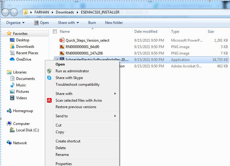
After we have downloaded the installation files, we will unzip the folder and start the installer.
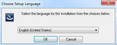
Select the language of choice for the software installation.
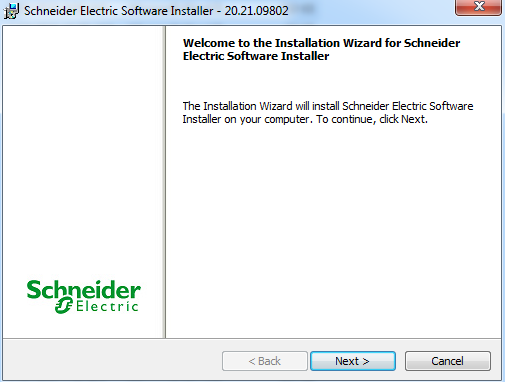
Next, we will see an installation wizard welcome screen.
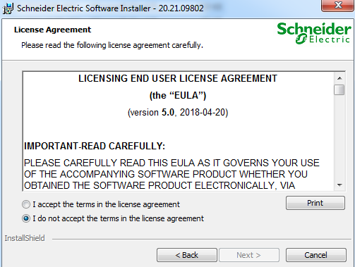
Choose the license agreement for the installation and begin the installation.
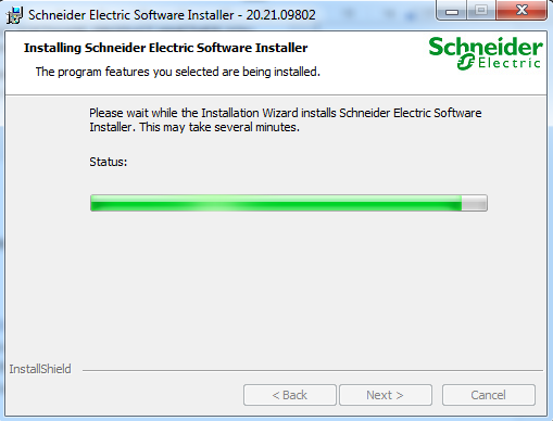
Schneider Electric Software installer progress will be shown.
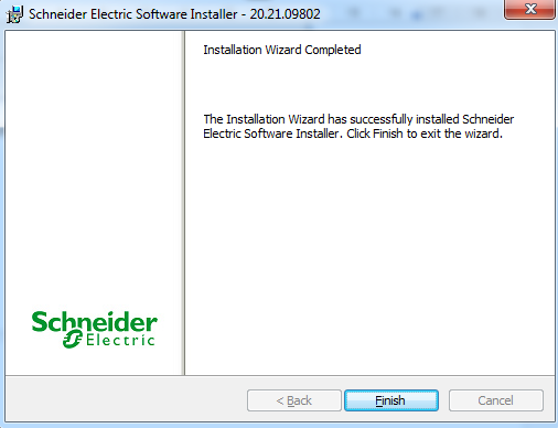
Once the Schneider Electric Software installer is installed on your PC, you will use it to download and install Schneider Electric Machine Expert V2.0.0.1.
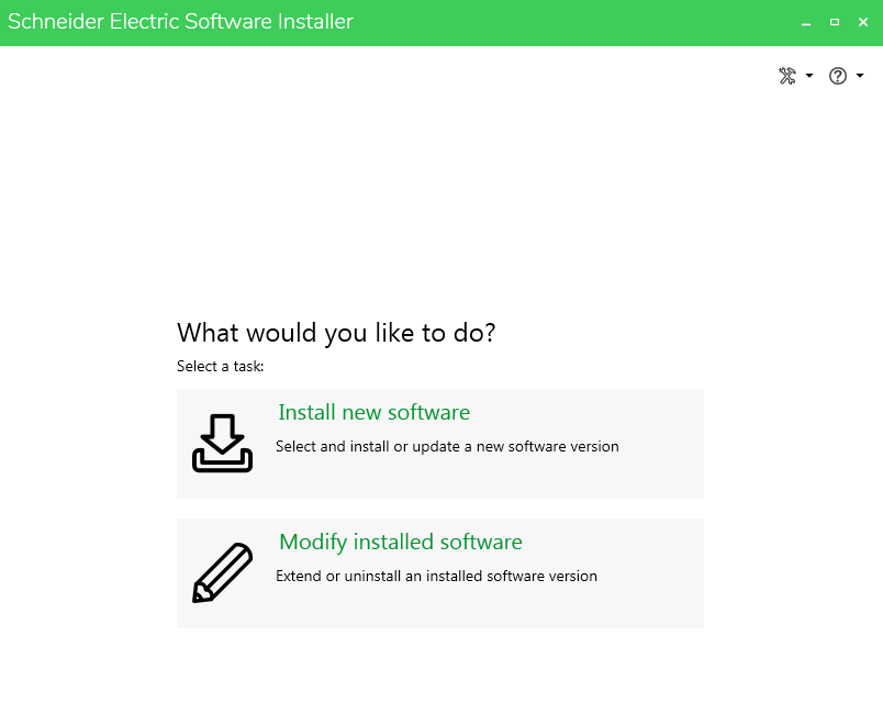
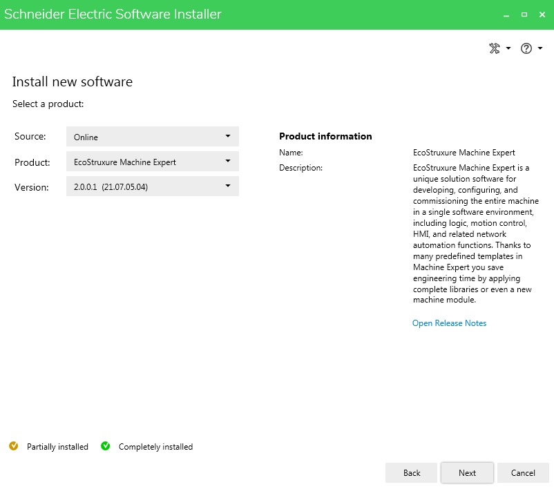
Now, we will choose the Install New Software option.
Select the source Online, product EcoStruxure Machine Expert and version 2.0.0.1.
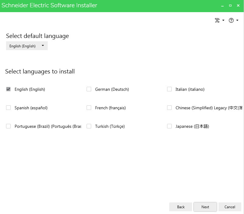
Select the language of installation for EcoStruxure Machine Expert.
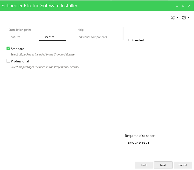
From the licenses tab, we can select whether we want the Standard or Professional installation based on the type of license we have purchased.
Accept the end-user license agreement and start the installation.
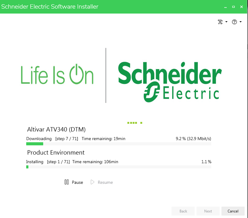
The progress will be displayed as the software gets downloaded and installed.
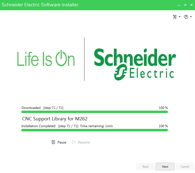
The software is now installed successfully and is ready to be used.
Creating a New Project in EcoStruxure Machine Expert V2.0
In this step, we will learn how to create a new project in EcoStruxure Machine Expert V2.0.
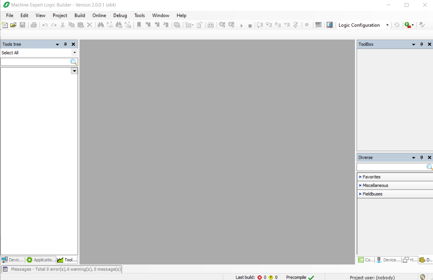
Once the software is installed, double click the EcoStruxure Machine Expert icon on your desktop which will open the machine expert logic builder window.
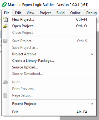
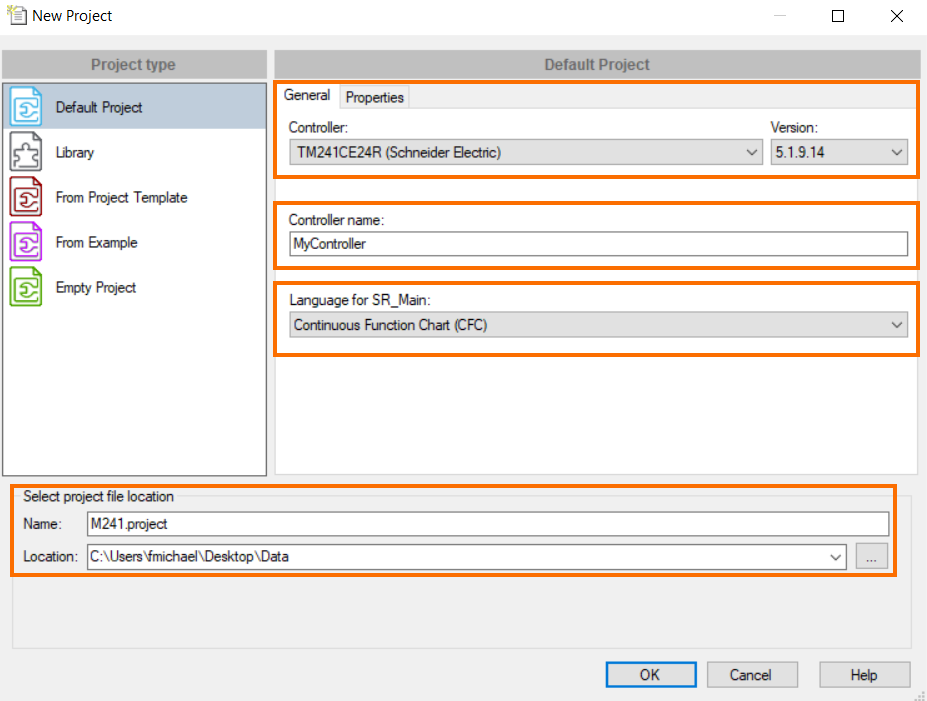
Once open, we will select File>>New Project. A new project window will open. We will select a controller (TM241CE24R), programming language, and give it a name.
Configuring Ethernet Communication
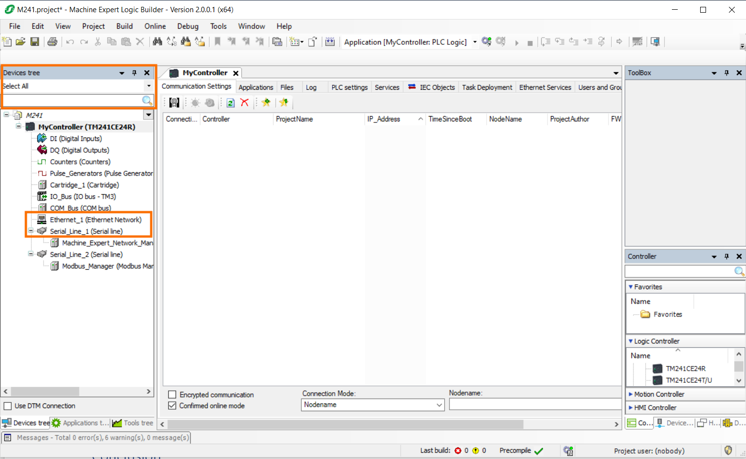
Once the project is created, we will start with configuring the ethernet communication by assigning an IP address to the controller. Select the “Devices tree” tab in the navigator window, and double click the Ethernet_1 (Ethernet Network) option.
Once the Ethernet_1 parameter window is open, input the IP address, Subnet Mask and Gateway address if needed.
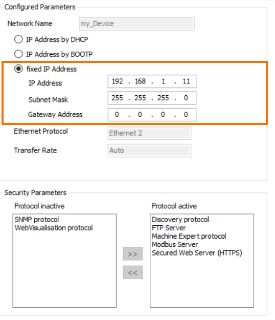
Save the settings by using the keyboard shortcut Ctrl+S or selecting the save icon on the toolbar.
Creating a POU (Program Organization Unit)
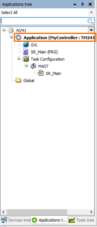
Now we are ready to create a new POU (Program Organization Unit). We will select the Applications tree tab and create a new POU (Program Organization Unit).
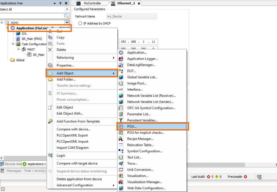
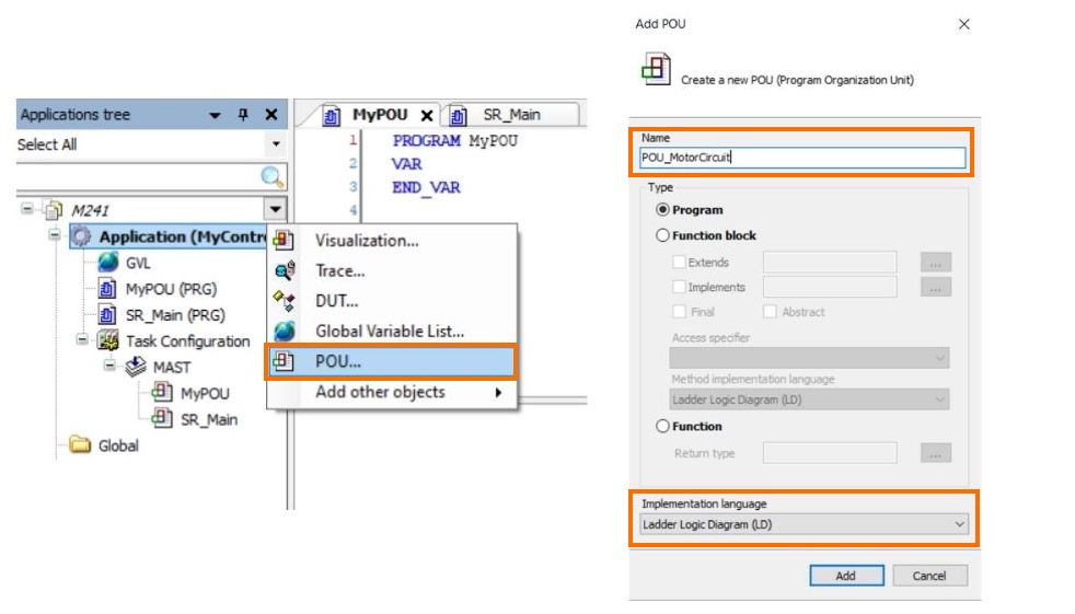
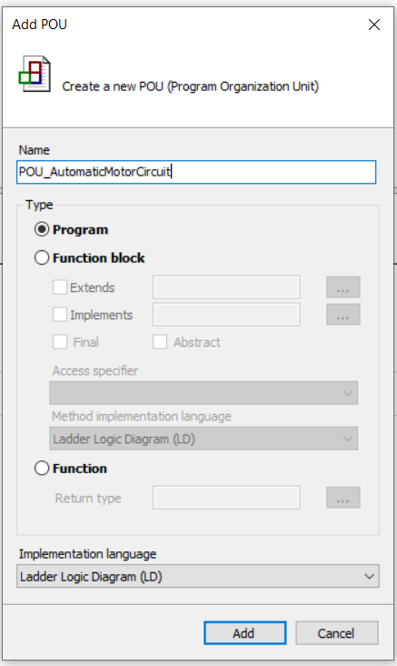
Right click on the Application (MyController:TM241CE24R) option and select Add Object. The Add Object option will expand into a sub-menu where we can choose POU.
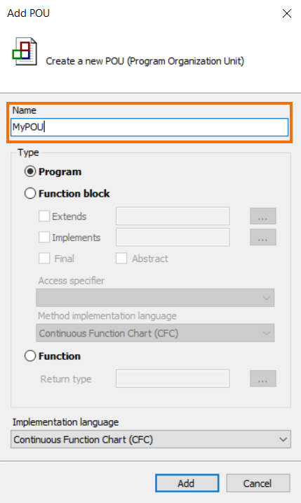
Once the Add POU window is open, select a name and preferred programming language.
Adding a POU to Task for Execution
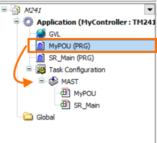
At this stage, we will add the POU created in the previous step to the Task Configuration. A POU must be added to the Task Configuration in order for it to be executed. In the Applications tree, select the MyPOU and while holding it with the mouse, drag it under the MAST.
Writing a PLC Program in CFC
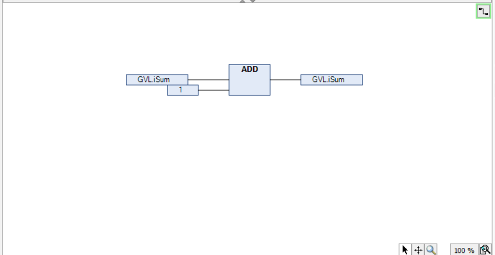
We are now ready to create our first program. We will create a short PLC program that we will download at the end of this exercise. The program will add 1 to a variable iSum and store the result in iSum.
In the Applications tree, double click the GVL option and this will open a Global Variable List. This is where we will create a new variable called iSum.
.png)
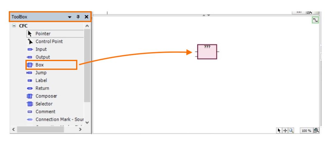
Next, we will drag a box from the Toolbox on the right as shown. Then we will enter the block from the library by typing inside the box for example “ADD”. You can assign the input and output pins by double-clicking and selecting the variables from the global variable list (GVL).
Save your project.
Writing a PLC Program in Ladder Logic
We will now add another POU (Programming Organization Unit) to elaborate more on programming in EcoStruxure Machine Expert Software.
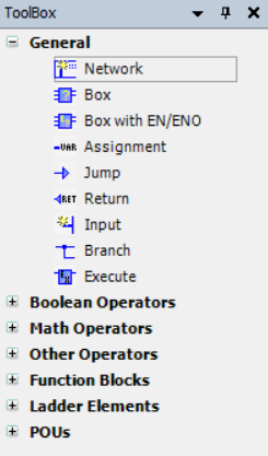
In this POU, we chose Ladder Logic as the programming language. This will change the options available in the ToolBox and the toolbar.

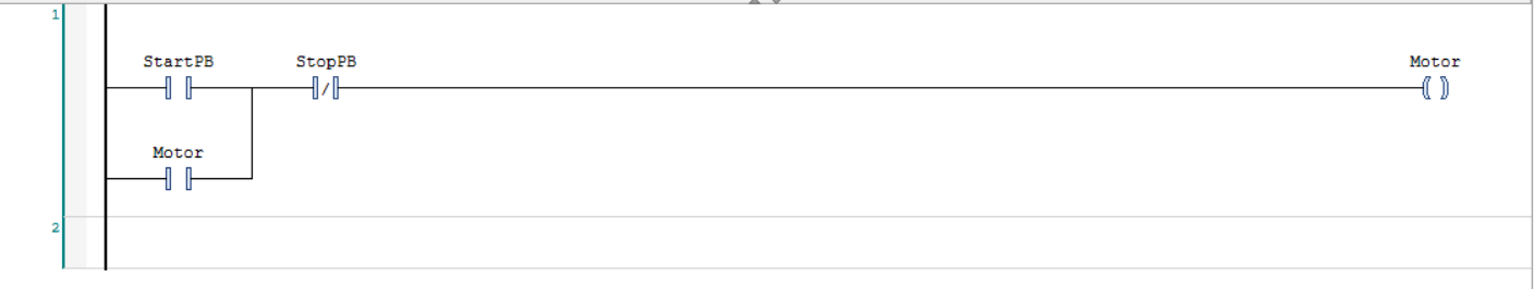
We will add a network and start adding the component. In this POU, we will create a motor circuit by adding a normally open (NO) contact for Start-PB, a normally closed (NC) contact for Stop-PB, and an output coil for Motor. Later, we will add another normally open contact in parallel with Start-PB to create a self-maintained circuit also known as Latch Circuit.
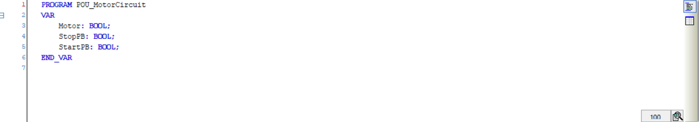
We will also define the three local variables of type BOOL to attach with those ladder contacts and coil as shown below.
The program will now look like this
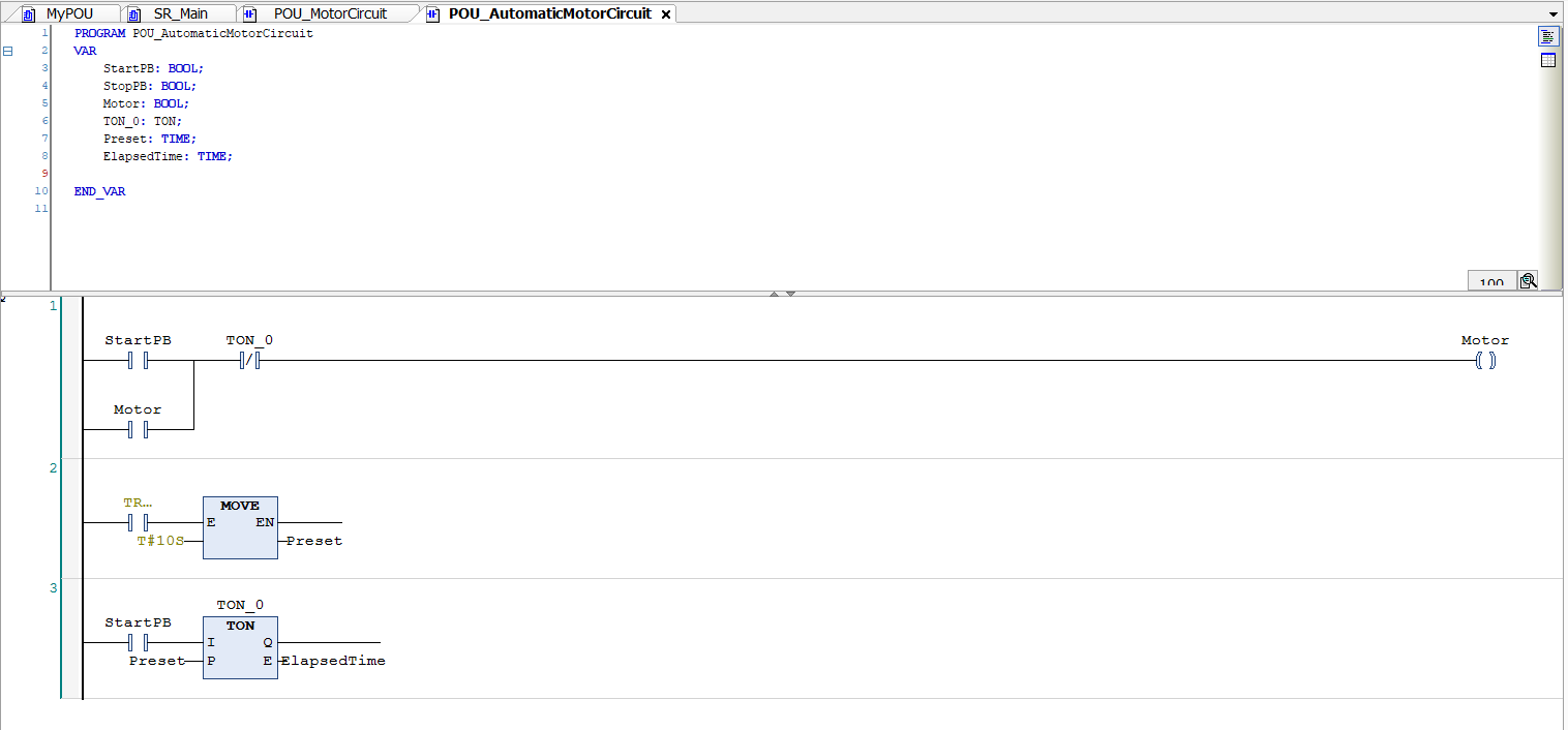
We can also add a third POU to the program for the automatic operation of the motor circuit with a timer block. This will show you how you can use an On-delay timer to keep the motor running for a certain time period.
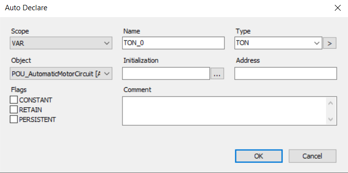
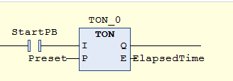
We will add a normally open (NO) contact for StartPB, a normally closed (NC) contact for StopPB and a TON timer block from the ladder toolbar. For the timer block, you will have to declare an instance such as TON_0 in this example.
The timer block requires to enable input (EN), preset time (PT), and Elapsed time (ET). The output of the timer block will be true once the timer has done timing. The timer requires a rising edge to start the delay counter.
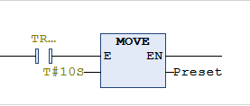
We are using a MOVE block to pass time preset value to a variable ‘Preset’ of type TIME.
The overall program will look like this:
Building a Project to check for any errors and warnings
In this step, we will build the project as shown in the image below. This is an important step to determine any errors in the program or project overall. The build will compile the code and the result will appear in Message Window.
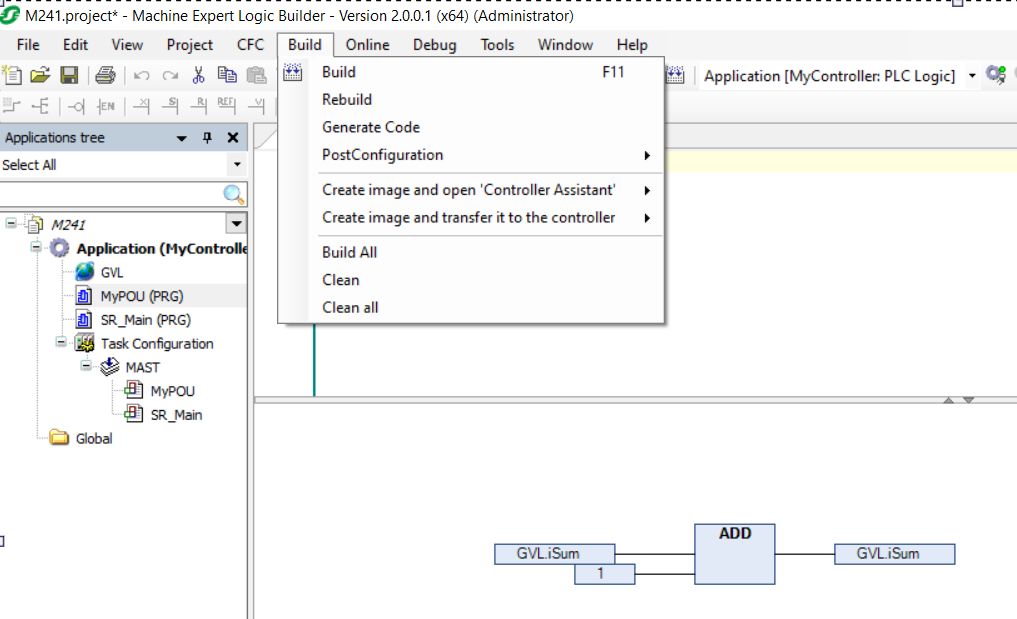
Select Build or F11 from your keyboard.
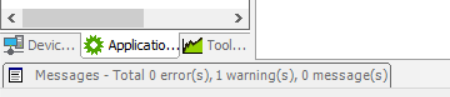
The message window will indicate if there are any errors in your project.
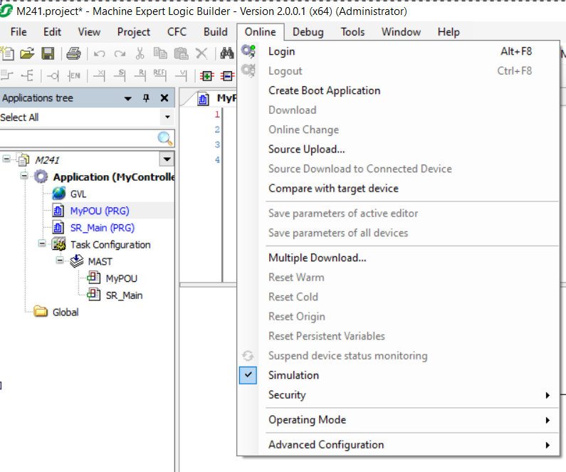
Downloading the PLC Program and Going Online
After we have completed the previous step, we will connect to the controller by accessing the Online menu from the menu bar. Select Login from the drop-down menu.
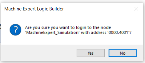
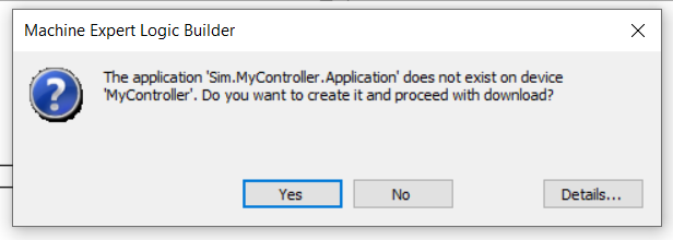
After selecting Yes, the PLC will connect and turn to STOP mode.

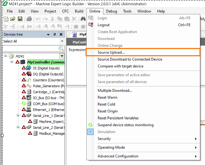
The source code can be downloaded to the controller if needed. Most OEM (Original Equipment Manufacturer) choose not to download the source code to protect their work. The source code is different from the compiled version of the code which runs during execution.
To change the PLC to run mode, we will select the ‘Debug’ menu and select ‘Start’.
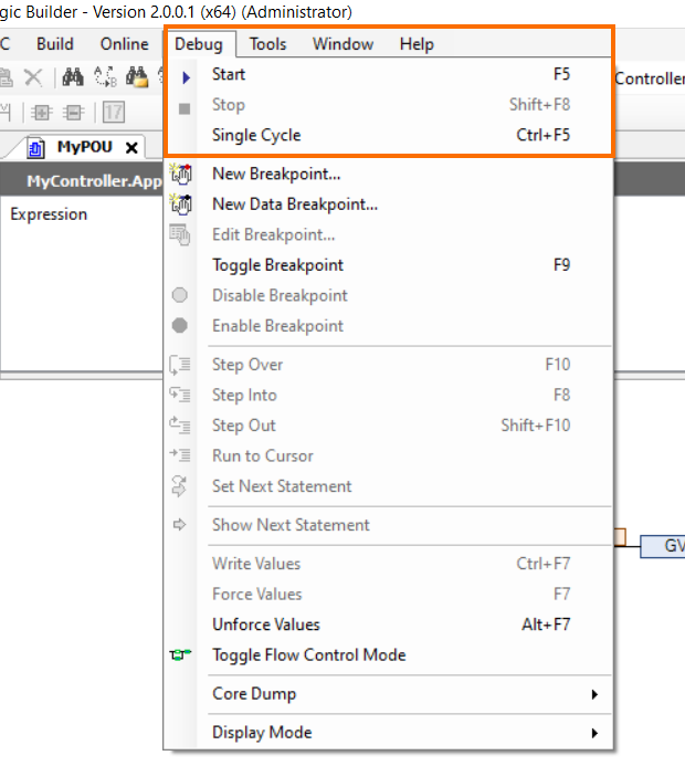
Choose Yes and the PLC will change to RUN mode.
Conclusion
This concludes the programming of Modicon M241 PLC using EcoStruxure Machine Expert V2.0. We have seen how to select the controller, give it an IP Address, create a POU and write an example program. We have also seen in this tutorial how to connect to the controller, download the program, and go online.
