An Introduction to Safety in Automation Systems
Introduction
By increasing productivity while battling a reduced skilled labor workforce, automation has given businesses an essential tool to be successful. However, while pushing these boundaries to advance ourselves, we must always remember that people are essential and must be protected.
While great advancements occur to push a company’s overall yield, safety risk should also be a major interest. The great thing about the innovations we have made in the technology is that it can help improve safety in our working environments so that productivity and quality do not deteriorate.
When automation first entered the workplace, everyone thought to bring the equipment to a stop before entering the zone to do any kind of work. Whether it was maintenance fixing an air leak or a production associate picking up a part that fell off of a conveyor, equipment must remain at a stop.
With this mindset, the first issue that occurs is downtime. The time it takes to safely bring the equipment to a stop, complete the task, exit the zone, and restart the equipment simply was not worth the downtime in some companies’ poor judgment or employees trying to make a production rate.
The second and most important issue is safety. Just because a piece of equipment is in a resting, potential energy state does not mean it is safe to work in the environment or around it.
As time goes by, we should all be aware that both mindsets are improper and safety does not have to be neglected to have a productive, quality process in place.
Safe in Automated Systems Best-Practices
Appropriate safety in automated systems should ensure that the potential risk for injuries is at zero for employees. Simply bringing all components to a stopped position is not enough.
A real-life example is - a production employee presses an emergency stop (estop) because a part was not loaded into a horizontal pneumatic press properly. The mindset of the employee would be to hit the estop when everything stops moving, then proceeding to reposition the part in the press window because it appears to be safe. However, has the air been dumped out of the press’s lines? Since it is a horizontal press, there is no gravity risk present such as a vertical press would have. However, if the lines are still under pressure then the risk of the press cycling could lead to a major injury or possible fatality. After hitting the estop the systems air should have been dumped from the supply lines and electrical power to components not involved in safety monitoring should be opened. All potential and stored energy must be released or opened so it cannot activate any non-safety components.
There are a plethora of safety components available to help ensure a safe, automated machine is available to protect employees and improve efficiency.
Emergency Stops
The most common safety device people think of is emergency stops or estops.
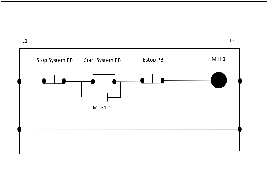
Emergency stops are commonly misused, and it is important to remember the purpose of a stop button versus an estop. An estop should be pressed when a hazardous situation or immediate protective measures must be taken. The emergency stop shall be a normally closed (N.C.) circuit so that when the button is pressed the circuit opens, ending all operations immediately and without delay.
A stop button allows the automated machinery in question to complete its cycle and come to a programmed stopped or home position (refer to figure 1.1 for emergency stop circuit). It may seem redundant to remind ourselves of this but we as programmers, control engineers, designers, end-users, or production employees should have this knowledge. Other forms of safety devices are light curtains, area scanners, and safety mats. Light curtains have a transmitter and receiver for laser beams that when broken open a circuit, stopping all equipment immediately.
Area scanners monitor a programmed area for any movement into that zone. Safety mats are designed to detect the pressure of someone standing on them. When the pressure is removed an estop effect is generating, opening a safety circuit, and stopping the automated cell instantaneously. By knowing how these safety devices work and installing them in the correct location an automated cell can always allow employees to be protected.
One of the fastest driving forces of automation in the workplace is robots. The use of robots can have a great effect on productivity and efficiency, however, the safeguarding of robotic cells is critical.

Robot Safety
While robots allow task(s) to be completed repetitively with accuracy, they are dangerous for people to be working around.
An initial safety analysis is the best place to begin. What operation and tasks are being completed by this robot? What kind of sequence is necessary, from initial start-up to programmed commands? How is the environment structured around the robot? How accessible are the robot and its cell for skilled and non-skilled labor? These are just some of the questions that we should ask ourselves and answer thoroughly to ensure a proper initial safety assessment is conducted.
We cannot just think of the programmers but also other engineers, maintenance technicians, and operators. Also taking account of what the process or job at hand is important. If the robot is gripping and moving a large item inside of a confined walled cell, then safety locked doors to prohibit are necessary. We would want to prevent the risk of an employee walking into the cell and the robot moving a large object, creating an impact/collision or crushing/trapping incident. While a programmed safe zone can improve safety mechanical limiting devices may be necessary to prohibit a robot’s movement into an employee work zone. ISO 10218-1:2011 defines a limiting device as a means that restricts the maximum space by stopping or causing to stop all robot motion.
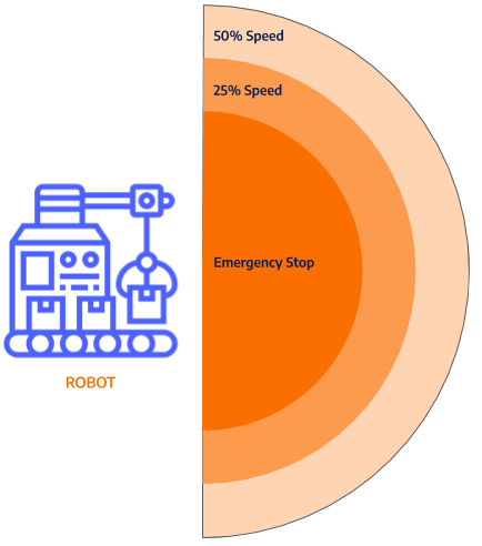
A new line of robots has been introduced to work alongside employees that have improved safety measures. This new line is known as collaborative robots. These robots are designed with built-in safeguards to allow them to be working next to employees. ISO requires them to use one of the four following safety measures: safety-rated monitored stop, hand guiding, speed, and separation monitoring, and power and force limiting (International Organization for Standardization, 2020). A safety-rated monitored stop is comparable to the traditional stops on industrial rated robots, it is a cycle stop. Hand-guiding-only safety measure is when the robot is only permitted movement via an operator controller. Speed and separation monitoring are inspecting its surroundings for workers (refer to figure 1.2). As a worker approaches the robot it continuously decreases its speed until the worker gets so close and it will stop.
When zone one, yellow, is entered the robot speed is reduced to 50%. The next zone reduces the robot overall speed even further, to 25%.
The last zone, in close distance to the robot, is programmed to activate the emergency stop circuit. Power and force limiting is the most common definition of collaborative robots in the industry currently. They have a decreased operating speed and payload limit so that the force exerted if they were to make an impact with someone is very minimal. Impact sensors within the robot cause them to instantly severe servo power. The power/force limit safety measure also means that the robots have a rounded, soft surface design to decrease the risk of injury.

Dual-Check Safety (DCS)
Dual-check Safety (DCS) is a safety control function that allows for specific safety boundaries to be created. The following tools are utilized within dual-check safety of robot systems; position check, safe zones, safety speed check, and cartesian position check. A position check is a programmed space that restricts where the robot can operate when performing its task.
DCS safe zones are set spaces that when personnel enters it a signal is triggered within the robot I.O. (inputs/outputs) to prohibit the robot from moving into that zone any longer. Safety speed check measures are utilized to reduce the robot’s speed the closer an operator is to it. Safety scanner zones can be set to monitor for personnel entry and upon triggering various zones the robot will slow down and, if close enough, come to a stop.
The last robotic safety measure is the cartesian position check. A programmer can define a real-world envelope for the robot and its end of arm tool to restrict movement. This ensures large grippers or other objects attached to the robot head are accounted for through its motion. Coupled with a programmable logic controller (PLC) allows us to communicate and control automated systems properly for optimal performance and safety measures.
Safety in PLCs
Programmable logic controllers, or PLCs, are industrial computers designed to monitor, control, and execute a custom program. PLCs are specially designed to be rugged and durable, able to withstand the industrial environment. Their original design and release aimed to replace the old hard-wired, relay logic of the past. Custom programs are downloaded onto programmable logic controllers that monitor the input feedback from devices, process decisions written in the program, and send outputs to varying devices to drive automated processes.
A recent innovation for the automated safety world is PLC safety modules. These new safety modules have redundancy designed into them to check for component failures, ensuring an unsafe condition is not introduced. This also simplifies safety circuit wiring versus the traditional safety relays and allows for easier troubleshooting. An important detail to add is that safety modules are allocated to a separate section within the PLC logic from the standard control modules, running exclusively on the safety processor. No electrical safety devices should be running back to standard PLC modules, they must be safety rated and meet specific requirements per ISO-13849 and IEC-62061.
Another key factor of a safety module is that they are dual-channeled with testing. Input signals are not only received on a terminal but a pulsing test node is also wired to very device integrity. These modules have received specific safety integrity level (SIL) and performance level-e (PL e) ratings to provide traceability and authenticity to their design and build for use in safety systems. We can install the best safety scanners and light curtains in the world on an automated cell but if we fail to properly monitor and communicate the occurrences then the system is not safe. On top of that, the safety modules in a PLC are only as good as the program within it. Proper logic within PLCs help keep people safe and going home every day.
Conclusion
Technology continues to progress with innovations and ideas presenting themselves rapidly. With an aging workforce and a declining interest in manual labor, factory jobs, and skilled positions, automated systems must be installed to maintain the needed production successfully. However, safety should never be overlooked and always the forefront concern. If we fail at keeping people safe by not implementing the right devices, standards, and programming then we are failing at our jobs.


