What is the RS-232 Protocol, What it's used for, and RS232 Serial Communication in Industrial Automation

Introduction
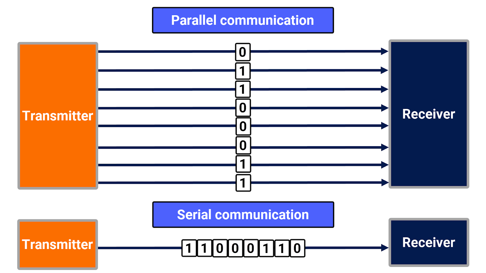
Serial communications, known for their simplicity and reduced hardware requirements compared to parallel interfacing, are widely adopted in the industry.
The concept of serial communication involves the transmission of data bits in a sequential manner, one bit at a time, through a specific communication channel. Parallel communication refers to transmitting multiple bits of data simultaneously across multiple channels, allowing for higher data transfer rates compared to serial communication.
In today's context, RS-232 is firmly established as the predominant serial communications standard. Often, you might hear the term 'RS-232' in the workplace, particularly from older and more experienced personnel.
Prerequisites
Prior familiarity with the 'PLC Networking Basics Tutorial' will prepare you to engage more effectively and enhance this tutorial comprehension, optimizing your learning experience.
RS-232 Definition
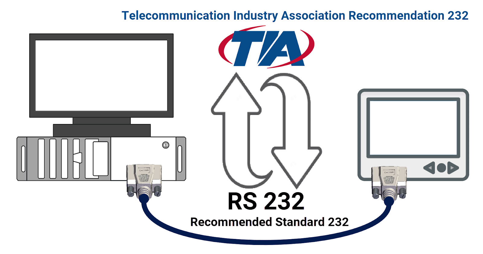
RS-232 is an acronym that expands to 'Recommended Standard 232.' RS-232 functions as a method for serial data transfer, serving as a recognized communication protocol that outlines the physical and electrical properties inherent to serial communication networks. Although RS-232 remains commonly referred to, it has officially been renamed TIA-232, derived from 'Telecommunications Industry Association Recommendation 232.'
RS-232 Connector
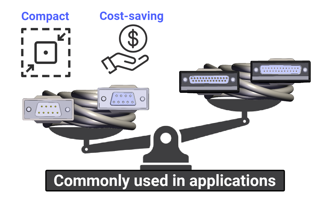
The RS-232 standard employs DB9 and DB25 connectors, each characterized by its D-shaped form. These connectors facilitate communication with their male and female interfaces on either end.
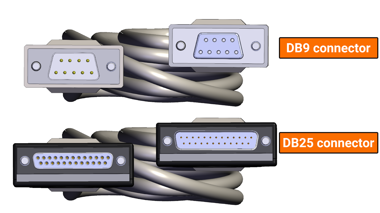
Given the limited utilization of most pins on the 25-pin connector within various applications in the industry, manufacturers embraced the 9-pin connector for its cost-saving benefits and its ability to occupy less physical space, thus optimizing device design.
RS-232 Pinout
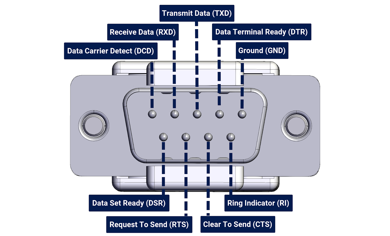
Since the DB9 connector is more commonly used in the industry, in this tutorial, you will delve more into the pinout for a standard RS-232 9-pin connector.
- TXD (Transmit Data): This is where data is transmitted to the receiver device.
- RXD (Receive Data): This is where data is received from the receiver device.
- DTR (Data Terminal Ready): This signal indicates that the terminal or transmitter is ready to launch a connection with the receiver device.
- DSR (Data Set Ready): This signal indicates that the receiver device is powered on and ready to communicate.
- RTS (Request to Send): This signal is sent from the terminal or transmitter to the receiver device to request permission to send data.
- CTS (Clear to Send): This signal is sent from the receiver device to the terminal or transmitter to grant permission to send data.
- GND (Ground): This is the electrical ground reference voltage.
- DCD (Data Carrier Detect): This is an indication from the data communication equipment that a carrier tone from the remote end has been detected.
- RI (Ring Indicator): This signal indicates the telephone line is ringing.
It's worth mentioning that the DCD (Data Carrier Detect) and RI (Ring Indicator) signals are primarily associated with modem applications and are less commonly used in modern computing and communication systems.
RS-232 Working Principle
Begin with two pieces of equipment that need to be communicated. To simplify matters, imagine one device only transmits data while the other only receives it. In reality, however, both devices perform both functions, but understanding communication in one direction allows you to apply it in both.
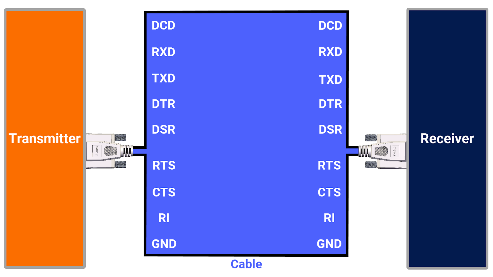
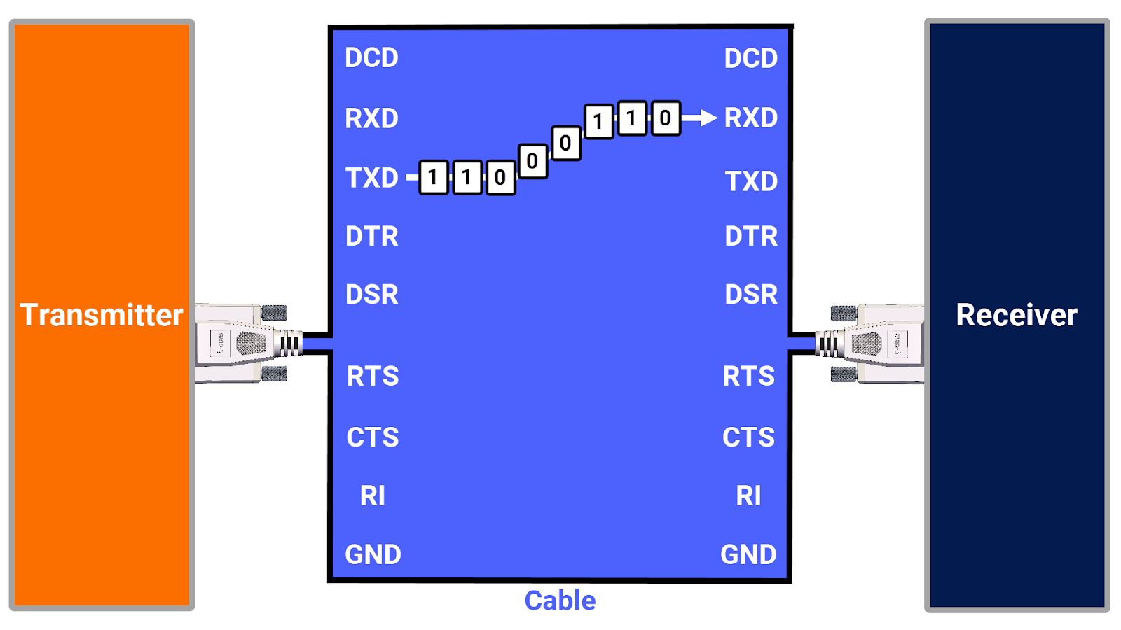
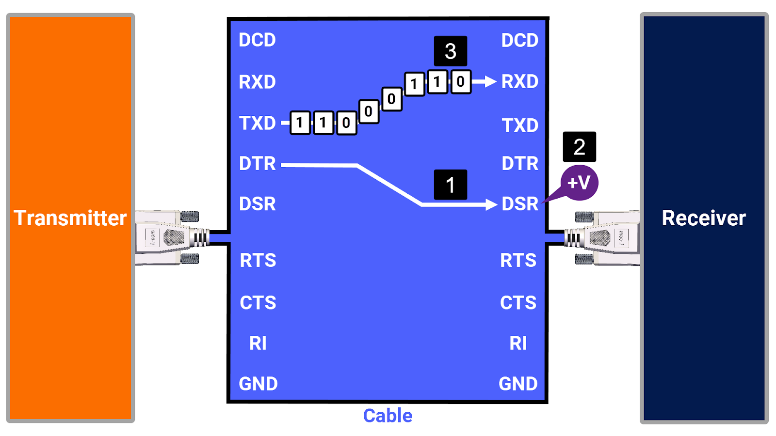
The data creation of the transmitter triggers the need for transmission through a physical wire to reach the receiver. This transmission is made possible by the transmit data (TXD) pin at the site of the transmitter and the received data (RXD) pin at the receiver’s end. Linking these links establishes an essential pathway, ensuring data flow from transmitter to receiver.
The RS-232 specification addresses scenarios where you want to ensure a receiver exists and is not absent for particular applications. But how?
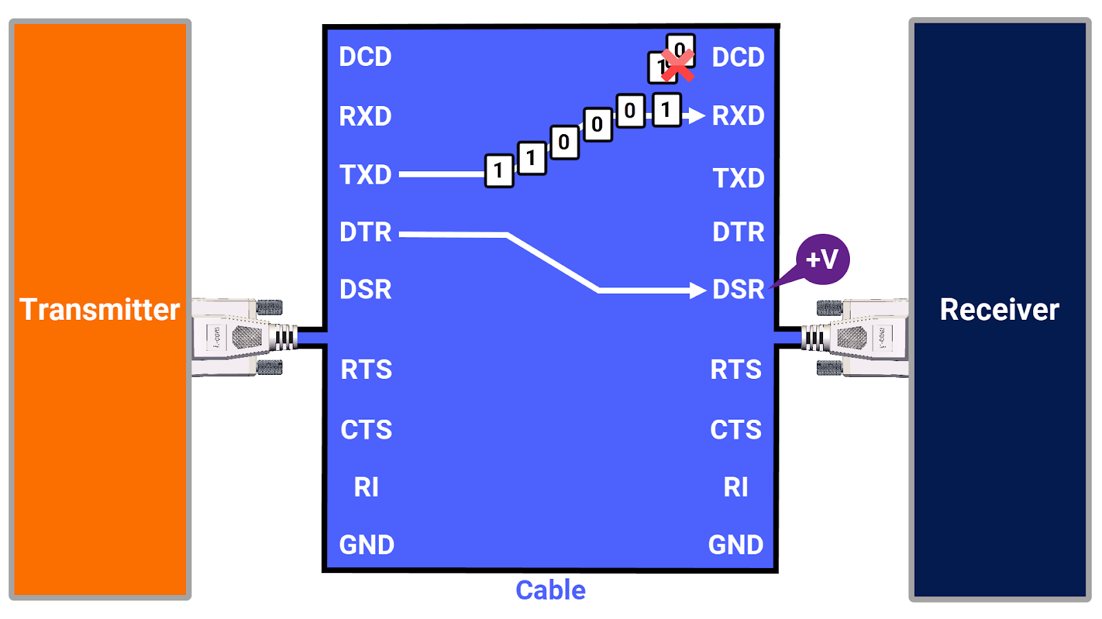
The RS-232 designers incorporated an essential control wire into the system, which communicates the presence of the receiver to the transmitter. This link, designated as Data Terminal Ready (DTR) on the side of the transmitter and Data Set Ready (DSR) on the end of the receiver, ensures that once connected and the receiver sets the appropriate voltage, the transmitter is aware that the receiver is there and present, thereby allowing data to be transmitted safely.
Another issue that may arise is the data transmission speed from the transmitter to the receiver. If the transmitter sends data too quickly, due to the receiver being unable to process the incoming data at that rate, it may result in data loss.
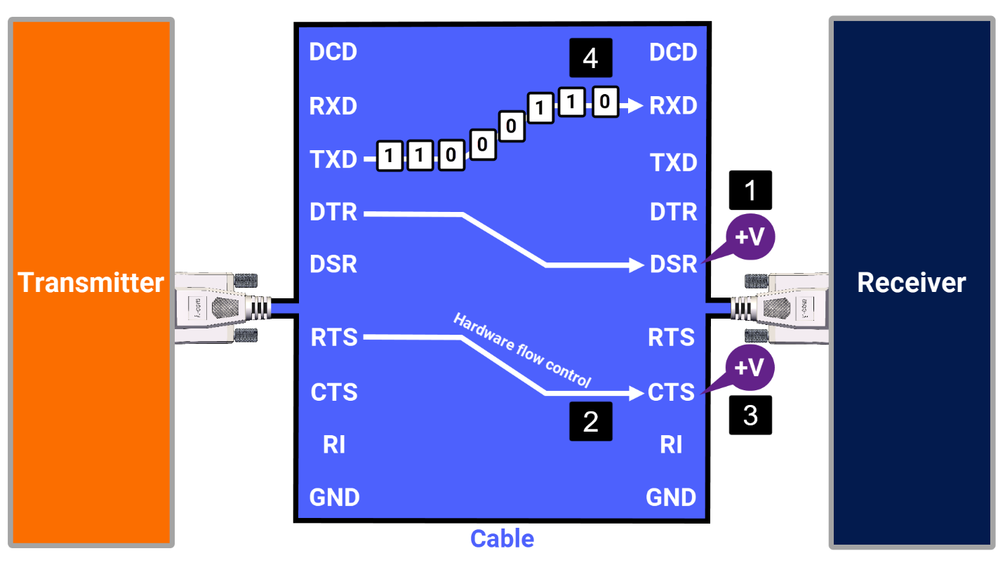
To mitigate the issue of coordinating data transfers, RS-232 designers introduced an additional control wire, which ensures coordination between the transmitter and receiver. This control is known as Request to Send (RTS) on the side of the transmitter and Clear to Send (CTS) on the receiver's end. When the transmitter is ready to transmit data, the RTS sends a request signal. Then, The CTS clears the path, indicating the receiver's readiness to accept the data. Once the path is cleared, data is sent from the TXD pin of the transmitter to the RXD pin on the receiver. This method, called hardware flow control, uses the RTS-CTS control to manage the data flow, ensuring efficient and reliable communication between devices.
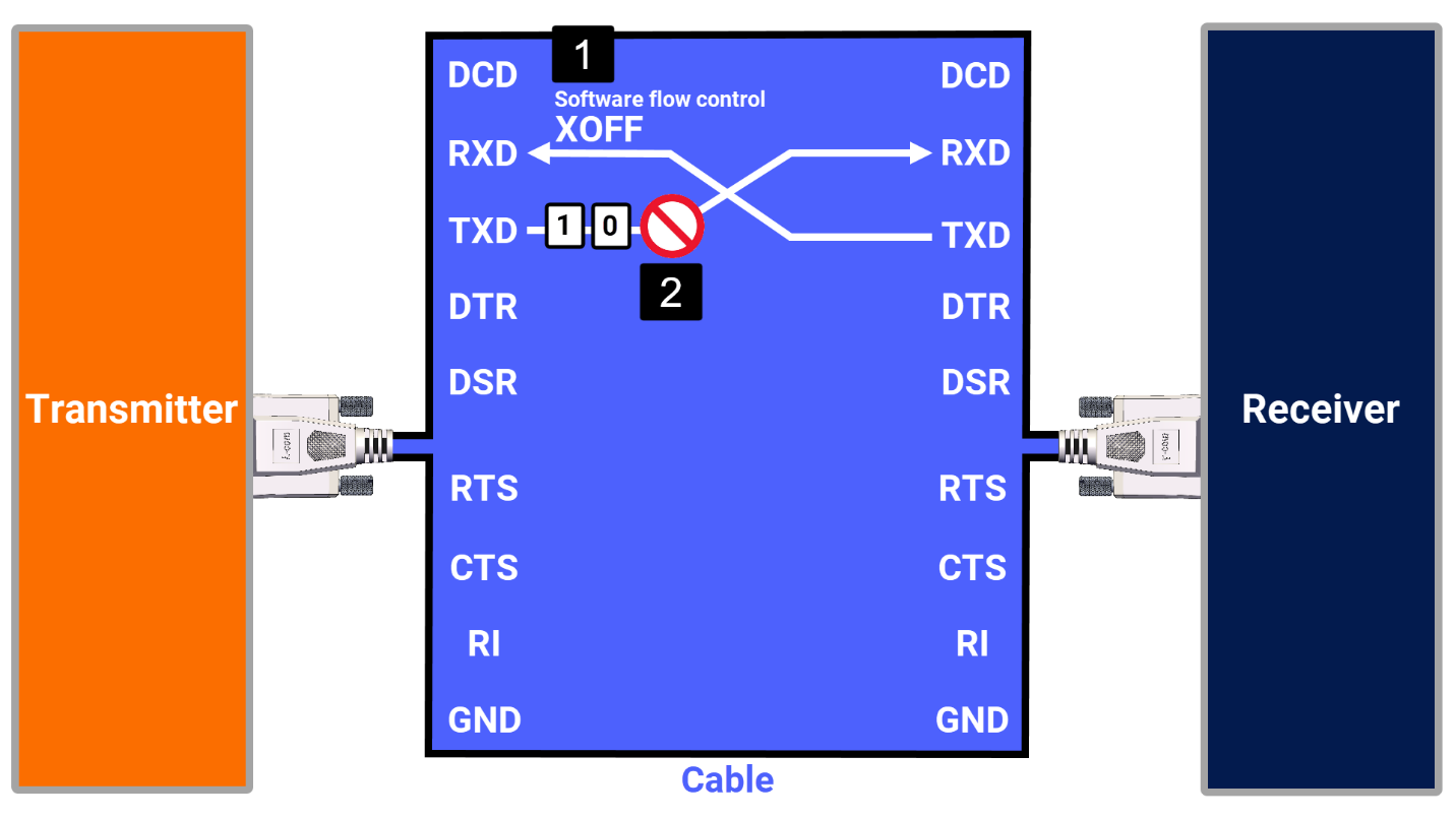
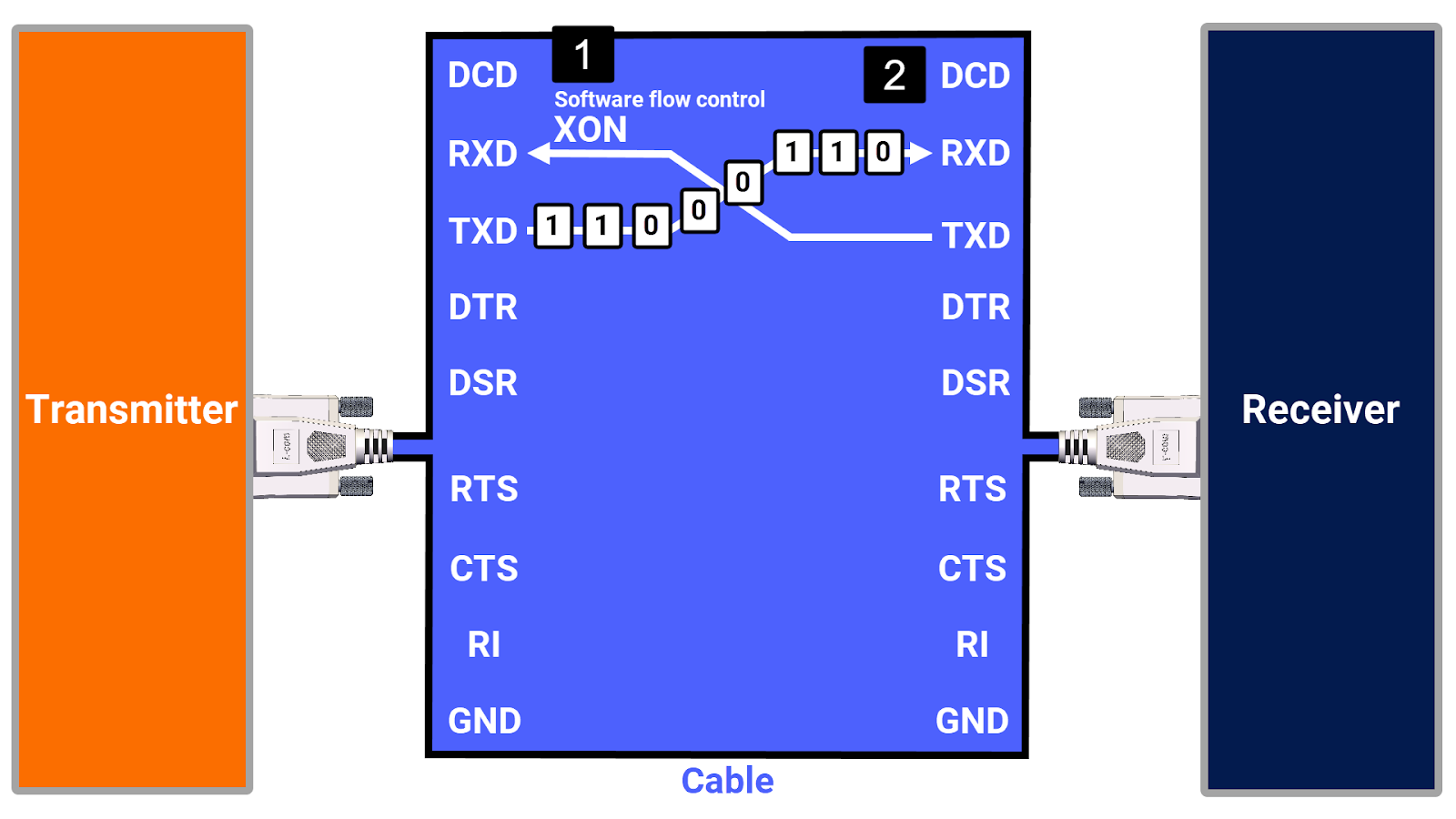
Besides hardware flow control, RS-232 also supports software flow control. When specific control characters (called XON and XOFF) are used to manage when data is sent from the transmitter to the receiver, it is referred to as software flow control. The receiver signals its readiness to accept data by sending an XON character to the transmitter. When it needs the transmitter to stop transmitting, it sends an XOFF character instead. Although this approach to flow control is less reliable than hardware-based methods due to the use of data characters for signaling, it typically performs adequately enough to be considered worthwhile in many cases.
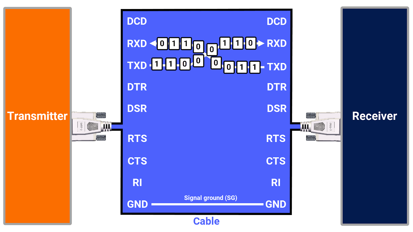
In the simplest case of transferring data between two devices using RS-232, you connect the transmit and receive wires. A third wire, the ground wire, is also necessary to maintain technical accuracy and ensure proper functioning. This wire, called the Signal Ground (SG), establishes the reference point for signal voltages. Therefore, the simplest communication form between the two RS-232 devices can be successfully achieved, using these three wires.
RS-232 Cables and Device Types
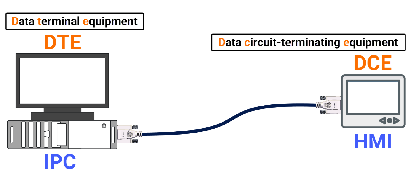
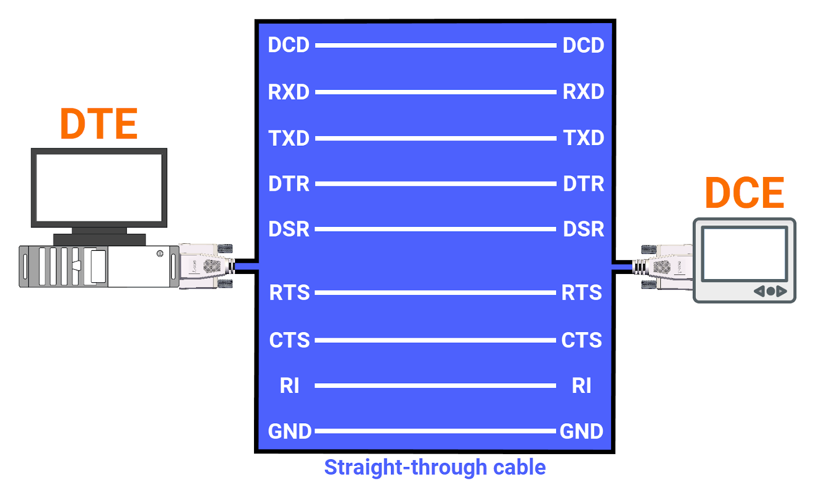
The RS-232 standard details the methods for serial data transmission, focusing on communication between a central system, called Data Terminal Equipment (DTE), and a connected peripheral device, known as Data Circuit-Terminating Equipment (DCE).
You can select from different RS-232 cable types, including straight-through cables, null-modem cables, and crossover cables, each tailored to meet distinct connection requirements.
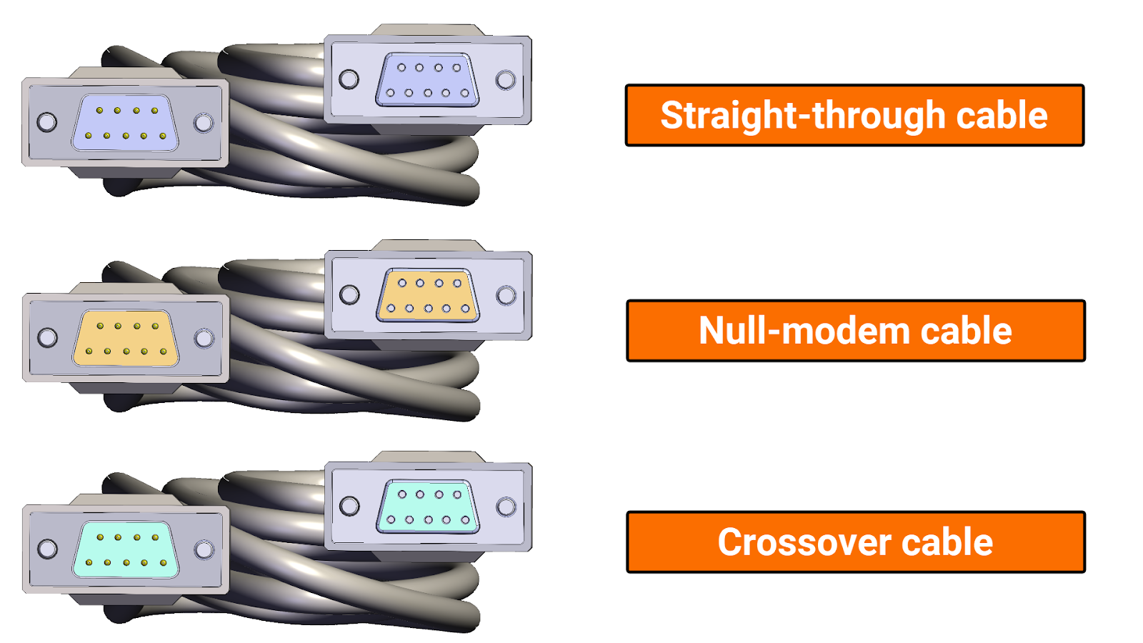
According to RS-232 communication standards, a conventional DCE device should be connected to a DTE device via a straight-through cable, which ensures that the numbers of pins on each connector are precisely matched.
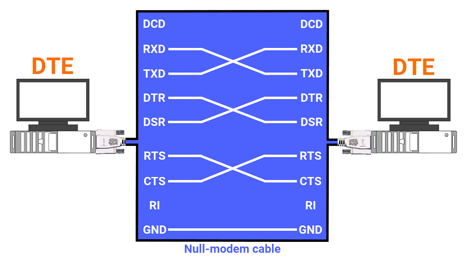
To connect two DTE devices directly, without a DCE device, a null modem cable meticulously reverses TXD (transmit data) and RXD (receive data) signals between Pin 2 and Pin 3 at each end. It ensures Pin 5 (Ground or GND) continuity and offers flexibility by crossing handshaking lines like DTR/DSR and RTS/CTS to optimize hardware flow management.
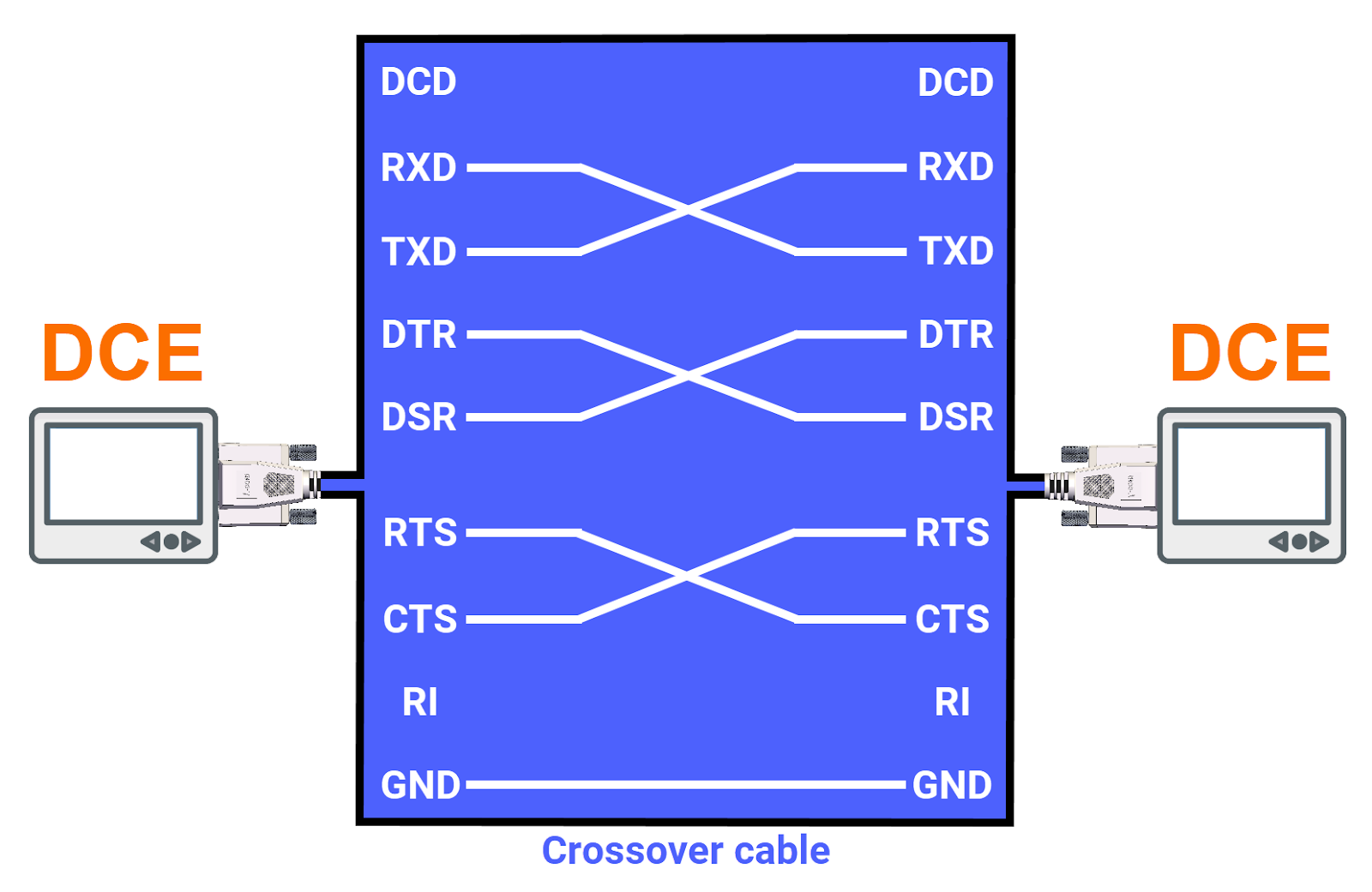
You can use crossover cables to connect two DCE devices, while connections between two DCE devices are similar to those made with null modem cables.
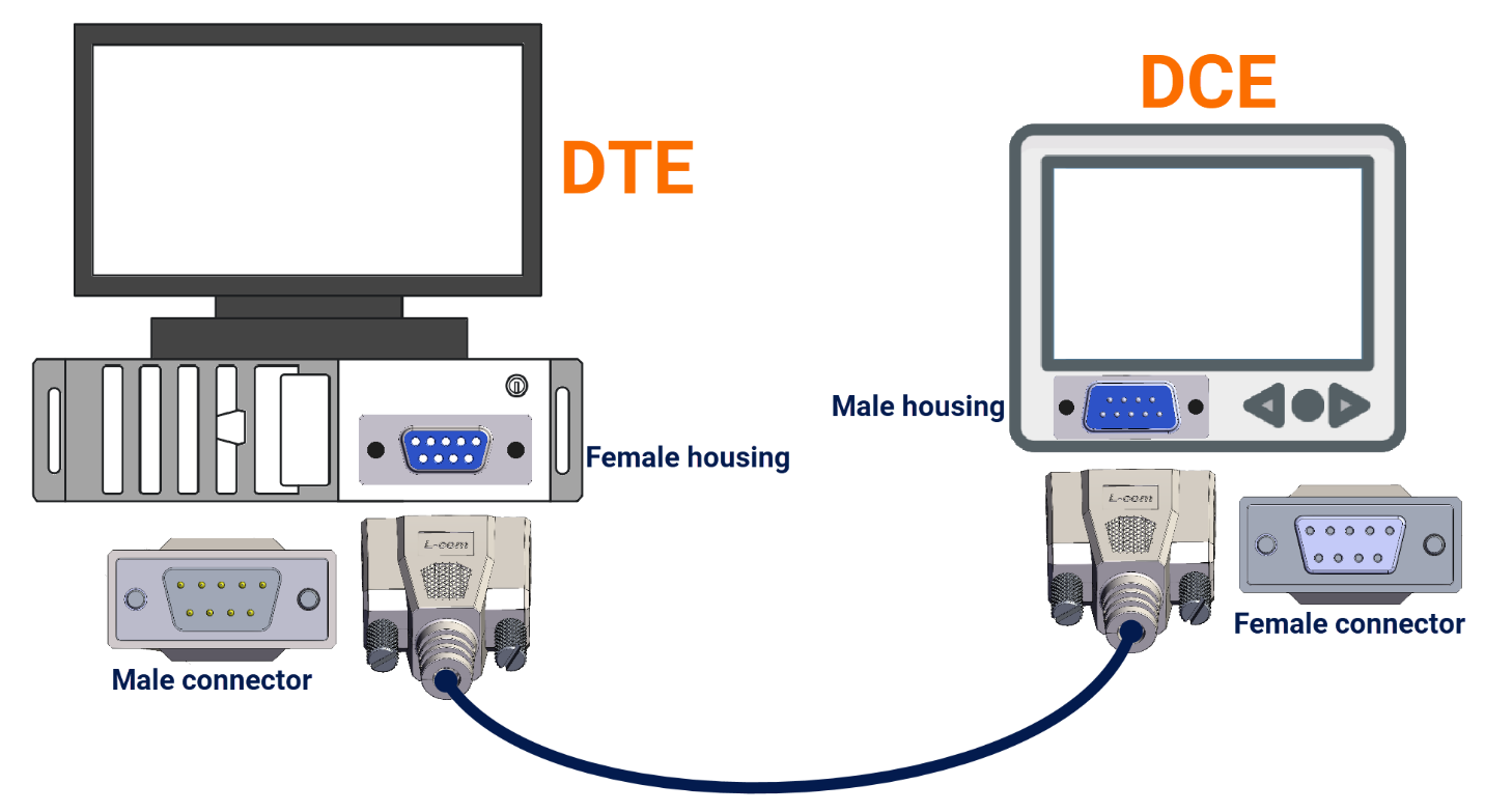
The DCE equipment connector boasts a robust design with a male housing intended for female pins, unlike its DTE counterpart, which utilizes female housing and male pins.
RS-232 Disadvantages
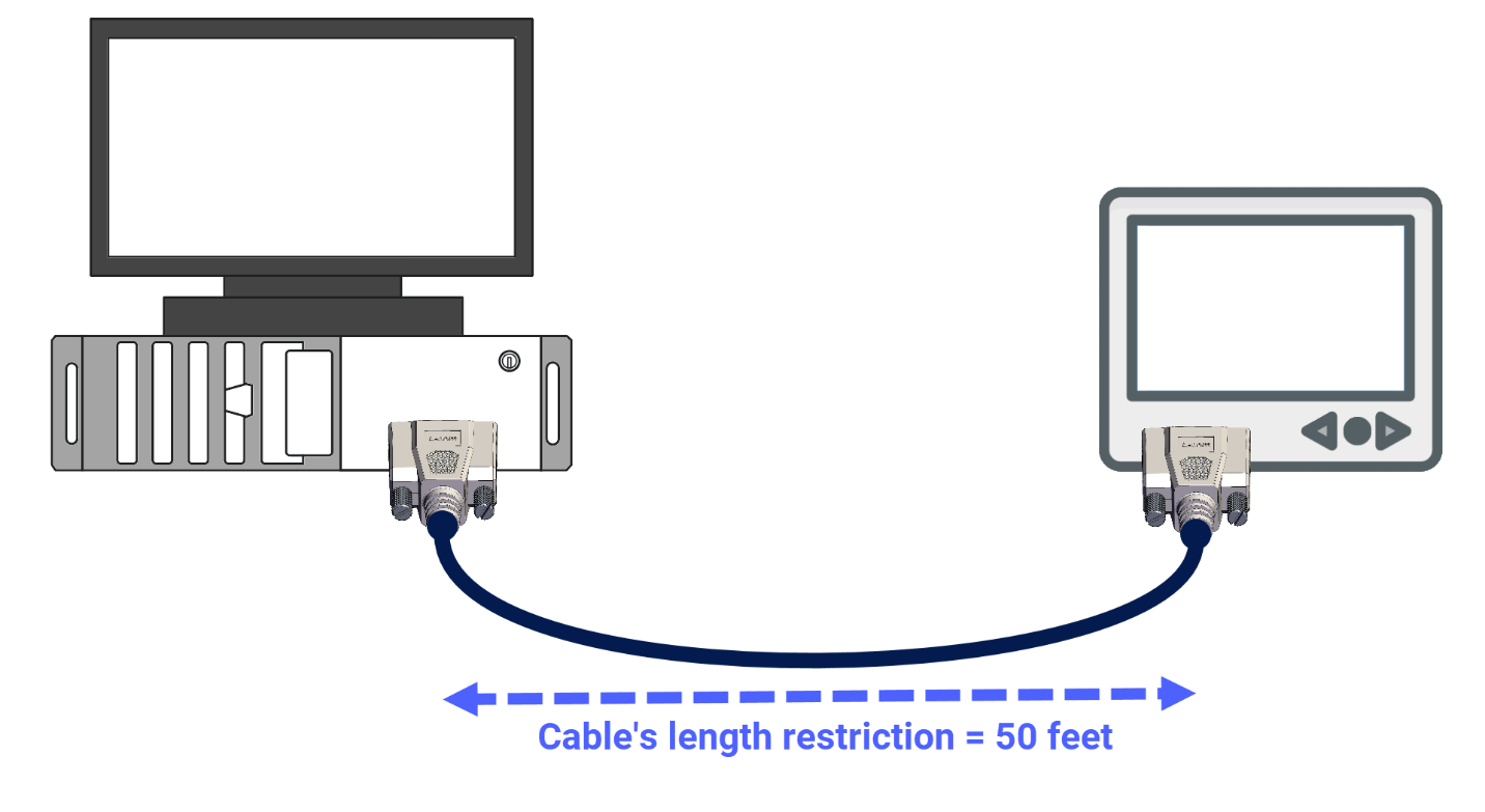
In this section, you will explore the drawbacks associated with the RS-232 protocol. The primary drawback lies in the cable's length restriction, which tops out at 50 feet. Beyond this threshold, issues arise from increased wire resistance and voltage drops.
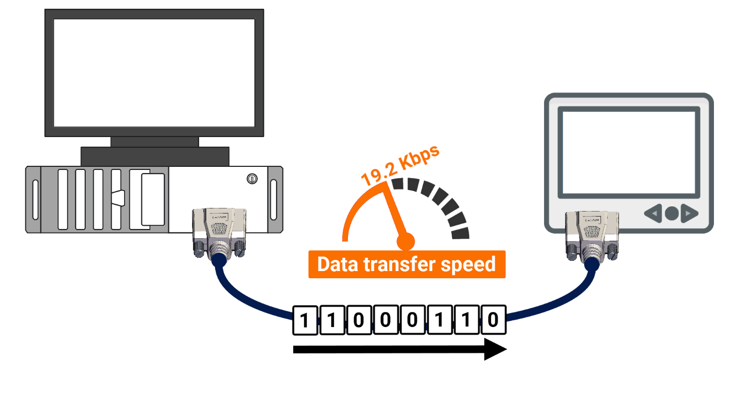
The second issue to address is the rate at which data transfers, typically hovering at about 20 kilobytes per second.
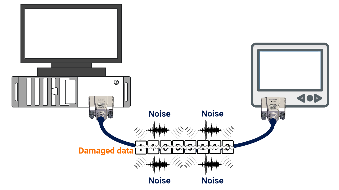
The operational reliability of RS232 cables can be compromised by radio frequency interference (RFI) and electromagnetic interference (EMI), which originate from diverse sources such as machinery and wireless communications, potentially leading to degraded signal integrity or complete loss of data transmission capability.
RS-232 Application
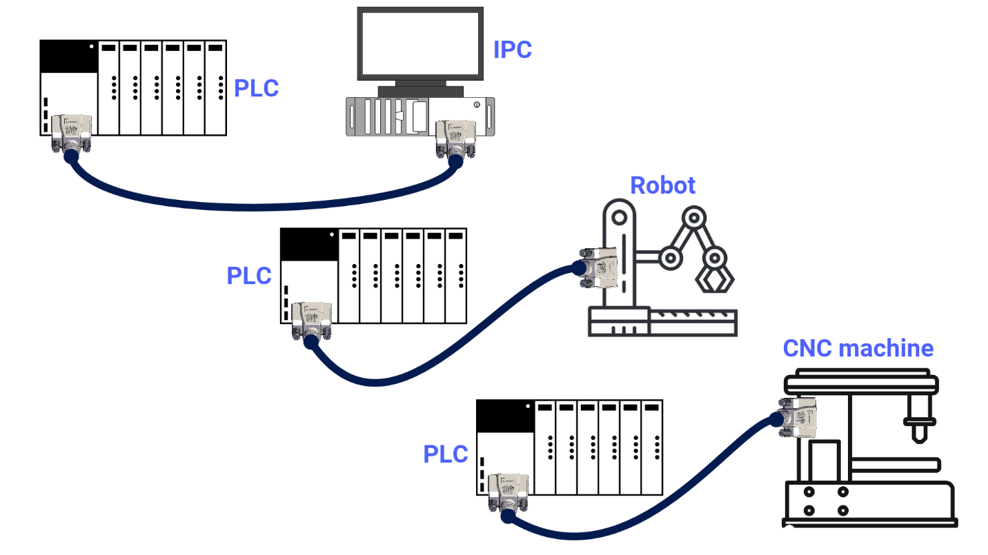
Within the industrial automation realm, the RS-232 interface remains a standard choice for applications requiring limited-distance, slow-rate, and point-to-point wired data connections that are sufficient for some tasks. For instance, some PLCs use the RS-232 standard to establish communication with instruments like HMIs, IPCs, robots, motor controllers, vision systems, CNC machines, and other similar equipment.
Conclusion
In conclusion, you learned about the RS-232 protocol, including its definition, connector types, and pinout configurations. You explored the working principles of RS-232, covering the essential components of data transmission and the hardware and software flow control methods. You also examined the various types of RS-232 cables and device configurations alongside the advantages and disadvantages of using this protocol. Finally, you discovered the practical applications of RS-232 within industrial automation, demonstrating its enduring relevance despite the advent of more advanced communication technologies. This comprehensive understanding of RS-232 will equip you with the knowledge to utilize this protocol in your professional projects.
