RSLogix PID Loop PLC Programming | Example of PID Control Instruction in Studio RSLogix 5000
Introduction
A PID control loop is a critical function within many industrial processes. It gives an engineer the ability to control a certain process based on the feedback received from field devices. Although this concept has a very extensive control systems background & theory, we’ve come to a point where we can utilize a PLC-based instruction to control the system without worrying about all the details.
As a control system technician, engineer or PLC programmer, it’s important to know how to deal with PID loops, how to create one, where it’s applicable, how to tune it, how to identify potential points of failure & have a basic understanding of the process in general. We will be discussing all of these points within this article as well as going over the process of creating a loop through an instruction in RSLogix 5000 & trending the output through the use of some basic logic routines & timers.
Fundamentals of PID Control Loops
As mentioned above, a PID Loop is a complex mathematical function which allows one to control a process based on certain feedback. Although you may choose to dive into the intricacies of the implementation of this instruction & begin to understand the theories behind it, the most important items are listed below. If you are capable of understanding their function & talk about their impact on the system, you’re in a good position to work with field PID loops.
- Process Variable – The portion of the system which is being controlled. In a heated tank system, the process variable is the temperature. This variable is obtained through a field feedback device: temperature sensor, position sensor, flow meter, etc.
- Control Variable – The system upon which you are able to exercise a force. In other words, something which allows you to have an impact on the process variable. In a heated tank, this would be the heating system. Other examples of control variables include speed setpoints of a pump, proportional valves, cooling & heating systems, etc.
If you have a difficult time understanding a control system in general, an excellent example is the speed control of a vehicle. As you drive on a flat road, you press the gas pedal with a certain force in order to achieve a target speed. As the road changes, for example, driving up a mountain slope, you realize that the force you’re applying to the pedal isn’t enough to keep the speed. You slowly start to increase the force until the vehicle is going at the target speed. Within an industrial environment, the same principle is applied to an array of different systems. A heating element will be controlled in order to maintain the temperature setpoint defined by the system. Similarly, a pump will be controlled in order to maintain a certain flow of a liquid.
- Proportional Gain – The “P” within the PID acronym. A proportional gain is the most fundamental scheme of control. As the process variable deviates further from the target, the control target will be increased. As the process variable approaches the target, the proportional gain won’t be as harsh on the control variable.
- Integral Gain – The “I” within the PID acronym. An integral control scheme will be based on the time the error is present in the system. It’s a hard concept to grasp, but going back to the vehicle example, this would lead to applying more gas as you see that you aren’t reaching the target speed.
- Derivative Gain – The “D” within the PID acronym. A derivative gain will monitor the error and determine the trend of the direction. If the error is decreasing, the derivative gain won’t have a large impact. However, as the error begins to increase, the derivative gain will start applying more force onto the control variable.
Basic PID Loop Programming in RSLogix 5000 / Studio 5000
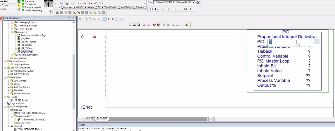
The implementation of a PID control loop on a Programmable Logic Controller is simplified in many instances through dedicated instructions. The PID Instruction within an RSLogix based PLC allows the user to implement the mathematical functions of a PID loop without the extensive knowledge beyond setting certain parameters. Here’s an example of such an instruction in Ladder Logic:

As a technician or engineer, you’ll need to specify the parameters for the instruction. The main variable is PID_CONTROL which has all of the back-end information on the specific loop. It’s also tied to the internal parameters. The Process Variable, as discussed above will be tied to the parameter which we’re trying to monitor within our system. For a heated tank, this would be the current temperature. Next, we have the Control Variable. This value will be tied to the piece of instrumentation which has an impact on the system and allows it to be controlled by the system. In a heated tank, this would be the contact which enables the heating element.
The instruction will require you to set a setpoint which is the target for the PID control loop. This variable is critical and can be changed by the PLC program in order to bring the process to the proper value. For example, the setpoint may be varied based on the recipe of the product as well as the stage the tank is in.
Some of the other parameters may also be set based on the PID type, but aren’t critical in most scenarios.
Tuning a PID Instruction – Proportional, Integral & Derivative Gains
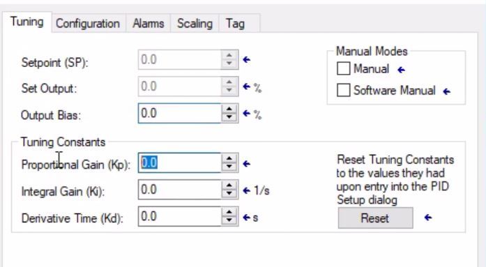
Proportional, integral and derivative gains will have a direct impact upon the performance of the PID loop you’ve defined for the system. Based on these values, the control loop will be more or less effective at controlling the setpoint of the process. The action of adjusting the values of these gains is called PID Loop Tuning. Here’s a short breakdown of the process.

- Start by setting the proportional gain of the loop to 10. Leave the other two gains at 0.
- As you trend the output of the loop through the process variable, adjust the proportional gain until you observe an oscillation of the value.
- Adjust the Integral Gain in order to dampen the action of the oscillation & bring it closer to the target.
- Lastly, adjust the Derivative Time which should close the gap between the current PID response and the target value.
As you observe an array of PID systems, you will develop an approach which works best for you; the above is just a good starting point and may not apply to all systems & heavily depend on the hardware as well as the process.
Simulating & Trending PID Loop Response in RSLogix 5000
It’s important to be able to simulate a PID loop in order to understand the operation as well as the impact of the parameters discussed above on the response. Simulating a PID loop without an active system is tricky and requires a timer which periodically updates the response of the virtual values directly on the PLC.
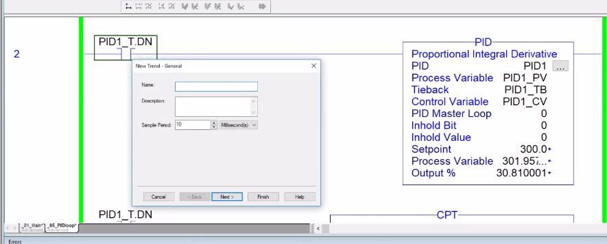
Building the logic for simulating the PID can be done as follows. Add a TON Instruction which is tied to a local timer. Update the PID as well as the process variable based on the completion of the timer. Here are the rungs which make this happen.


The CPT Instruction is used to calculate a new Process Variable based on the deviation of the PID loop. Although this logic isn’t extremely accurate of a real system, it can be used to observe the impact different variables play on the loop. It’s an excellent way to practice trending as well as observing the PID loop implementation without an actual system.
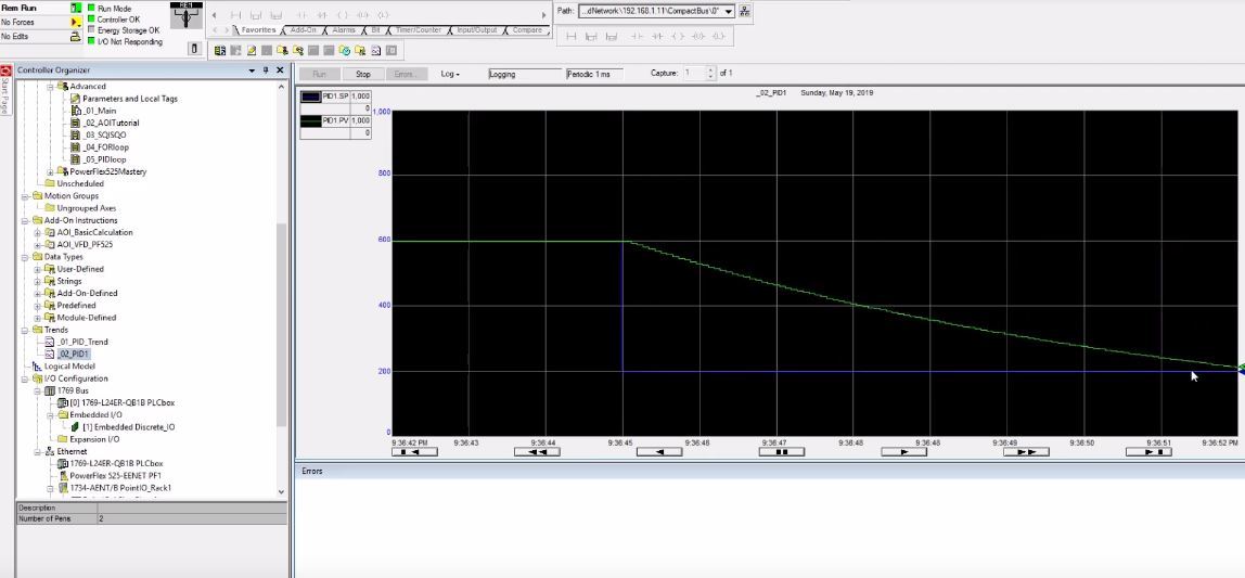
Trending can be used for any tags in RSLogix & Studio 5000. This is an extremely useful practice which allows you to easily observe a PID loop, tune the parameters & see if there are any issues. Start by adding the PV (Process Variable) and SP (Setpoint) tags to the trend & observing the reaction of the loop to the changes of the setpoint. As you adjust the three gains discussed above, you will see different responses.

Field Challenges of Working with PID Loops
The PID Instruction can solve many inefficiencies of a system. However, it’s not something which can be applied to any situation. It’s important to understand some of the shortcomings as well as unusual situations within the PID instructions & be able to rectify them through other means.
Improperly Sized Control Systems
A PID system relies on the fact that the control mechanism is able to adjust the system into a steady condition. In other words, a heater which is heating a tank must be able to provide enough energy in order to raise the temperature to the desired level. Should the heating mechanism be undersized and unable to heat the tank while the control system is calling for a steady ON signal, the loop will never be able to achieve what it’s designed to do. The engineering team will need to go back to the drawing board and either increase the heating capacity or increase the insulation.
In a flow-based application, if the recipe calls for 10000 pounds of product/minute & the pump was sized to provide a maximum of 8000, the PID loop will never be able to achieve this result. It won’t be the solution to the problem.
Ineffective or Defective Feedback Mechanisms will Amplify Problems
The PID loop heavily relies on receiving proper feedback about the current status of the system it’s designed to control. A sensor which isn’t designed for the application or isn’t supplying the right information will throw it out of control. In most cases, you won’t be able to adjust the parameters in order to counter the problems with instrumentation.
A feedback mechanism may be inadequate for reasons which aren’t inherently tied to the sensor. For example, a flow-based system which is controlled by a valve over 30 feet away from the flow meter, may experience problems. These problems are due to the fact that the feedback loop is too slow and as the liquid propagates, the feedback is sent 30 seconds later. In a steady state condition, the loop can be tuned for a continuous flow, but at the beginning, it will struggle as it needs to be much more aggressive.
Control Gains aren’t Easily Reapplicable
Based on the nature of the system, it’s hard to migrate the same values between the system. Each one needs to be tuned independently unless they are completely identical. Having the same starting point is fine, but relying on the same values will most likely result in frustrations.
Conclusion
A properly applied & tuned PID loop is extremely effective in many industrial processes. However, technicians, as well as engineers, often misunderstand this instruction due to its complex mathematical nature. As you practice using the PID instruction, you’ll quickly notice that the implementation is much simpler than expected. In fact, most of the science behind a PID is obstructed by the PLC logic.
In an RSLogix 5000 based PLC, the PID Instruction can be implemented in Ladder Logic, tied to an input signal and be told to control an output based on the gains set in the configuration. By simulating the instruction on the controller, it’s possible to practice working with and observing this instruction in action.


